-
-
February 11, 2024 at 12:41 pm
Eduardo GarcÃa
Subscriber
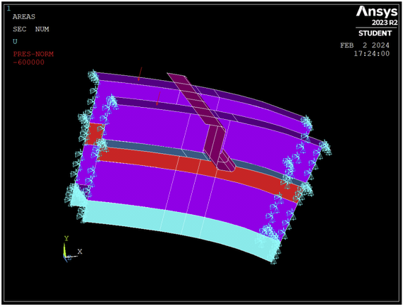
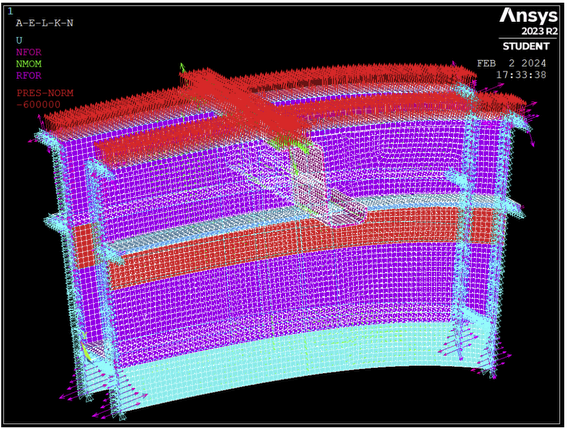
Hello, I've been struggling with applying a pressure load to a shell element for a while. I'm trying to simulate an outward pressure on a plane´s frame, but the results make no sense to me. The propper setup of loads is displayed in the next picture, while both lateral sides are fixed:
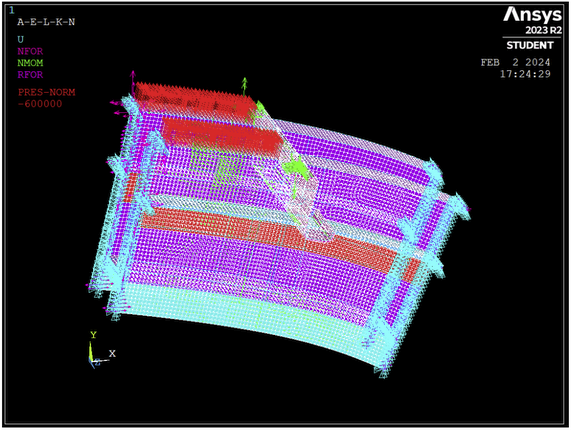
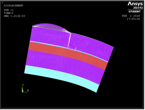
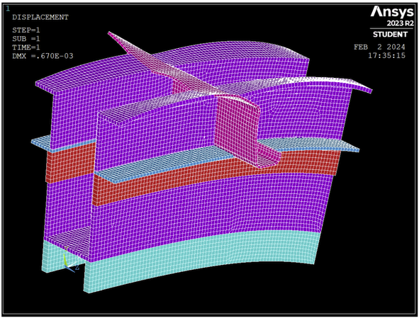
If I apply a comun pressure, since it is an imported geometry, some loads appear to be facing outwards and some others inward, so I've been told to change sign of the pressure applied to those faced in the wrong direction (inward). However, If I do so, I get the second picture's results, which, I'm told are the right solution. There I can see the parts I changed the load on are going down and those who I didnt change going up, when all should have the same response, an upward bending.
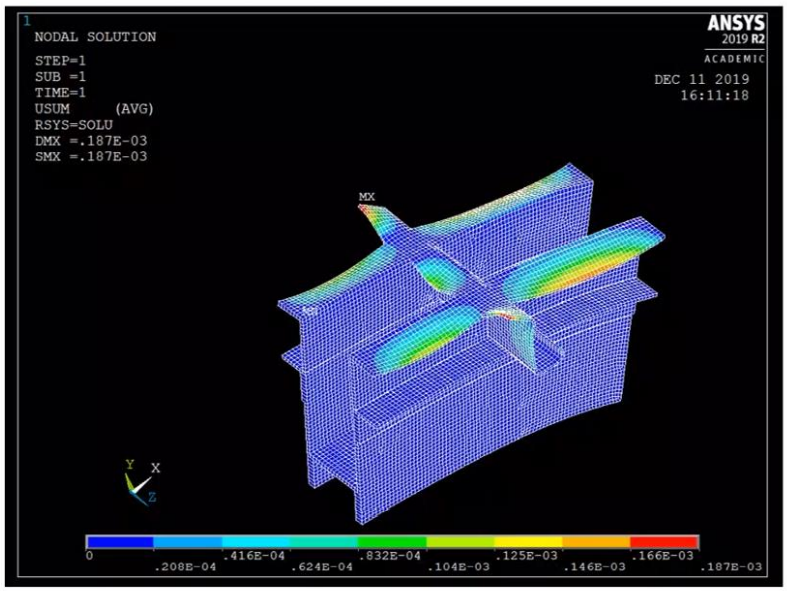
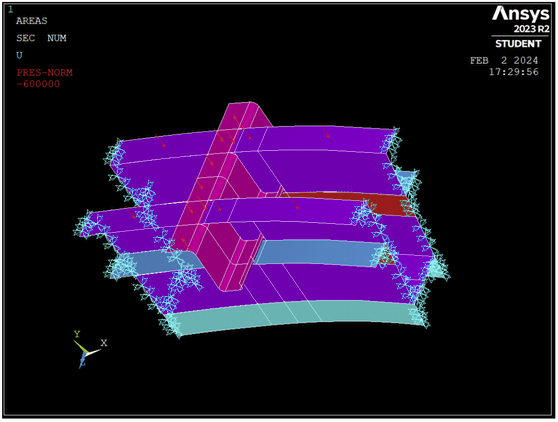
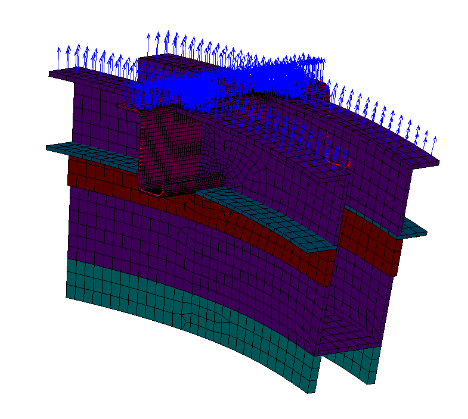
So, instead, I went back and give every surface the same load and sign, getting the las picture's results, which make a lot more sense to me, but I'm told that is not correct. Can someone explain what is going on with the pressure load direction and how is it posible that a positive pressure results in an opposite bending?
Thank you for your time
-
February 11, 2024 at 1:50 pm
peteroznewman
SubscriberI agree the contour plot from Ansys 2019R2 looks wrong and the contour plot from Ansys 2023R2 looks correct.
The pressure arrows look correct. Which version of Ansys were they clipped from?
It's possible that 2023R2 interprets the imported geometry differently than 2019R2 did.
-
February 11, 2024 at 5:38 pm
Eduardo GarcÃa
SubscriberHello,
the first 2 pictures are taken from the .pdf solution, so I believe they both should be from the same version, 2019R2. However I've conducted the same experiment on the 2023R2 version getting the same results. For example, If I apply the same pressure during the preprocessing phase on only a couple of surfaces like the ones shown below, the pressure seems to be facing one direction, but if I take a look element to element, that direction changes. The final solution seems to resemble that of the second picture.
If I apply the same presure to the whole surface in the same version, arrows point both directions, but in the same way as the previous case, when I look element to element everything seems all right, and the solution is as I expected to be, an upwards bending. But I'm told that I must change that pressure over those areas so that the first arrows face the same direction, but that gives me the faulty solution I posted before, which makes no sense hahaha
-
February 11, 2024 at 7:57 pm
-
February 11, 2024 at 8:30 pm
Eduardo GarcÃa
SubscriberIn that picture all the arrows of every element are facing the same direction, upwards, which is opposite to the previous one, showing a single arrow on the surface pointing downwards. When applying to the whole upper area of the structure (picture 4 of my reply), both upward and downward arrows appear over the surface , but when I take a look on every element (picture 5), they all suddenly point up somehow. As a result, the whole structure bends upwards.
It seems the correct direction of the pressure load is seen when looking at elements, and not to surfaces alone. Yet my professors insist on changing that direction so that all arrows point the same way on the surfaces view, messing all up and giving a mix of bendings both upwards and downwards.
-
February 11, 2024 at 10:09 pm
peteroznewman
SubscriberOh, now I understand your confusion.
The single arrow on the face of the surface geometry is pointing in the direction that a positive pressure will push the surface based on the surface normal of the geometry. You entered a negative pressure, so the arrow on each element flips to show the direction the pressure entered will be pushing.
Surfaces have a normal direction and it is possible to flip the normal direction in CAD.
Elements have a normal direction and it is possible to flip the normal direction in the preprocessing software.
By default, elements will acquire the same normal direction as the surface that was meshed.
Changing the sign on the pressure will cause the arrows on the elements to flip direction.
If you were to flip the surface normal in CAD, then the direction on the geometry view would show the arrows pointing up. After you mesh those surfaces, the normal arrows on the elements will point up if you enter a POSITIVE pressure. Then the material will deform upward. This is what your professors want to see. I'm sorry they could not explain this to you.
-
February 12, 2024 at 6:57 pm
Eduardo GarcÃa
SubscriberOk, I understand a bit more now about normal directions. Still, in my reply surfaces have both arrows pointing up and down (picture 4), yet elements only have arrows pointing up (picture 5). Since I've applied the same pressure to all of them, -600 kPa, it seems some follow the surface's normal, and others don't, as they don't change direction by that - sign. Those surfaces pointing down do follow the surfaces normal when meshing, changing direction by that - sign on the elements load view, but those pointing up don't.
Seeing that, applying a +600 kPa pressure to those surfaces which have an arrow pointing down, which is what I'm told to do, will result in a pressure going down, as they follow the surfaces normals. This will result in the problem I was struggling, some parts wouldn't have an upward pressure after that change, so they wouldn't resemble the real problem in this picture.
-
February 12, 2024 at 10:42 pm
peteroznewman
SubscriberThe only thing that matters is the element force arrows. Maybe Ansys meshing software is clever enough to notice that some of your surface normals point in an inconsistent direction compared with most of their neighbors and makes the element normals point in an appropriate direction. I don't know if it does this but it seems that it is doing that. Other vendor's software I have used is not that clever and I have to fix the element normals manually.
I expect if you flip the surface normal on the inconsistent faces of the geometry and then mesh that, Ansys will continue to deliver appropriate directions on the elements.
-
February 12, 2024 at 11:44 pm
Eduardo GarcÃa
SubscriberI couldn't understand what was happening but that seems reasonable. Thank you very much for your help, I really appreciate it, I was stuck with this for quite some time.
-
- The topic ‘Pressure direction problems on shell elements’ is closed to new replies.
-
6485
-
1906
-
1458
-
1308
-
1022
© 2026 Copyright ANSYS, Inc. All rights reserved.


