TAGGED: fluent
-
-
October 17, 2022 at 11:24 am
GIRISH PATEL
Subscriber
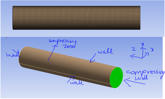
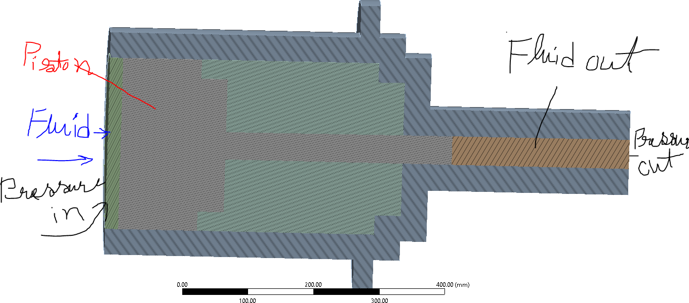
I have a simulation of simulating a pressure intensifier. I want to find the pressure attained in the compression chamber after the piston moves by ‘x’ stroke length. I have made a moving mesh simulation.
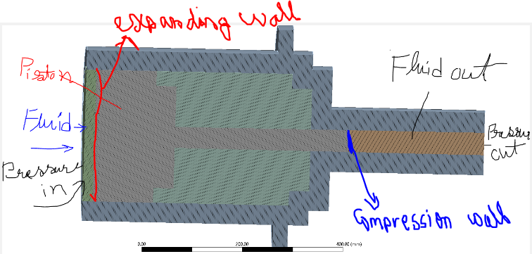
In this the compressing wall is moving at a velocity of 0.1 m/s. I have defined an UDF. The compressing wall is defined as a rigid body motion. The compressing zone is assumed as deforming zone.
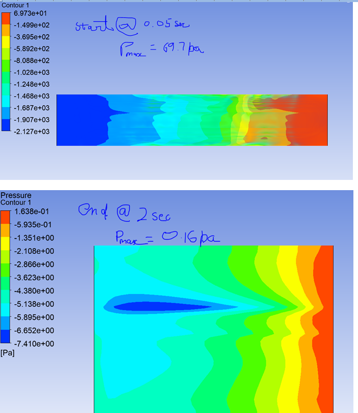
I have simulated the simulation with standard k-e model. Water as the fluid. Simulation time steps of 200 time steps with time step of 0.01 sec. Total simulation time of 2 seconds.
The problem is in the results. The pressure obtained at the start of simulation is more than the pressure obtained at the end of simulation. Where have I gone wrong?
UDF:
#include"udf.h"
static real velocity = 0.1;
DEFINE_CG_MOTION(box,dt,vel,omega,time,dtime)
{
NV_S(vel, =, 0.0);
vel[2] = velocity;
Message("time=%f, vel[2]=%f\n", time, vel[2]);
} -
October 18, 2022 at 10:07 am
Rob
Forum ModeratorWhat is the water density?
-
October 19, 2022 at 3:53 am
GIRISH PATEL
SubscriberThanks for the Replying Mr.Rob.
The water density in our case is 1000 Kg/m3
-
October 19, 2022 at 8:22 am
Rob
Forum ModeratorSo, to summarise. The volume is getting smaller but the water density is fixed. Where is the extra mass (or volume) going?
-
October 20, 2022 at 5:18 pm
GIRISH PATEL
SubscriberHi Rob, My Study aims in designing a intensfier that gives high pressure output for low pressure input. My Intensfication Ratio is 27 times.
The Diagram shows the Piston and cylinder with area reduction, The Piston is pushed from left to right, by the fluid (Water Liquid). Dynamic Motion mesh is applied to the Fluid(left side) at a velocity of 0.1 m/s.
For our case the Fluid shoud move making the piston also to move, such that the pressure difference is achieved and Higher Pressure is obtained at the Right end.
so How should I proceed as the software requires Input Pressure and Velocity both to attain the Output pressure as Per Pascals law P1A1=P2A2.
The first Diagram posted 2 days back shows that the Compressing fluid at the right end corner of the System. For the udf attached to it and the velocity given. The Fluid is not able to attain the pressure as per Theoretical Calculations.
I Request to guide me, how to Perform this Problem in Ansys Fuent.
Thanking you
Girish Patel
-
October 20, 2022 at 5:34 pm
GIRISH PATEL
SubscriberThe Water will not go anywhere, In real the design consists of Inlet Valves and outlet valves incorporating fluid direction control valves and flow control valves. in which the fluid when entered from right, pushes the piston until the end, that makes the small end piston also to move pushing the prefilled fluid residing at the right end side of the cylinder. alternatively to and fro motion is experienced by the piston giving the Pressure difference.
-
October 21, 2022 at 10:16 am
Rob
Forum ModeratorOK. If you want to model the liquid flow it has to have space to move: squashing liquids can be done but it's often not needed. If you want to add a pressure into the system and look at a piston moving which then displaces liquid at the other end you may want to look at Mechanical with some fluid elements. We can do it all in Fluent using moving mesh, 6DOF etc but the cost is much higher: it's worth paying if you need all of the information.
-
October 25, 2022 at 6:36 am
GIRISH PATEL
SubscriberWe would like to do in ansys fluent with moving mesh along with piston and inlet pressure. What is the correct methodology ? Since the compression zone is compressing, in the current simulation I have given an UDF to the Compressing wall. As per your suggestion, how should we modify the UDF ?
If we just give inlet pressure, then we do not know at what speed the piston moves. So we do not know at what rate the compression zone is compressing or the expanding zone is expanding. If we want moving mesh how do we specify the velocity for the compression wall compression, expanding wall expansion and piston ? movement
-
October 25, 2022 at 7:00 am
GIRISH PATEL
SubscriberWhat I mean is, during the deformation of Dynamic mesh, I need to define the expanding wall, Piston and compressing wall as Rigid Body Motion. A rigid body motion need a UDF. How do we specify the UDF when we do not know at what velocity the Piston is moving ?
How can we make Fluent to automatically move the piston, expanding wall and compression wall as per given input pressure ? (The velocity might vary with different pressure)
-
October 25, 2022 at 8:44 am
Rob
Forum ModeratorCheck the 6DOF options too. Instead of giving the velocity directly you'll need to link it to the force balance. Pressure on the "in" end, back pressure "out" end and friction+inertia for the piston. There's also any compressibility/leak effects of the middle green-ish section.
-
October 25, 2022 at 3:42 pm
GIRISH PATEL
SubscriberThankyou Rob, I will try it as you mentioned.
-
- The topic ‘Presssure Intensifier Simulation with moving mesh’ is closed to new replies.
-
6450
-
1906
-
1457
-
1308
-
1022
© 2026 Copyright ANSYS, Inc. All rights reserved.
