TAGGED: ansys-ls-dyna
-
-
October 31, 2024 at 6:17 pm
mostafam
SubscriberHello everyone
I am trying to model a column of soil consisting of 100 equal solid elements, where the nodes of each elevation are constarined in all directions of x,y,and z to behave completely in shear. The materials are elastic and all are the same.I also fix he bottom of my column in vertical direction. When I apply prescribed_motion_set at the bottom of the soil column (in x or horizontal direction) and my motion would be displacement, after doing the analysis, the nodout shows significantly crazy values for acceleration at the bottom (where I apply the dispalcement as my input), however, the other nodes have rational acceleration records.
Does anybody knows what am I missing?
I am using ls-prepost for my simulation.
Thanks
-
November 5, 2024 at 3:45 pm
Pedram Samadian
Ansys EmployeeHi,
Would you please provide an image that shows the model with the boundary conditions applied to different nodes? What element type and shape did you use in the simulation? Please also provide a graph showing how the rotational accelaration changes with time in those nodes.
Based on the current description of the model, the nodes of each elevation seems to be over-constrained for a pure-shear loading condition, and their applied boundary conditions need to be modified. You may find some hints regarding the required boundary conditions for such a model in the following sources:
1- Dense Granular Columns in Liquefiable Ground. I: Shear Reinforcement and Cyclic Stress Ratio ReductionThanks,
Pedram
Â
Â
Â
-
November 6, 2024 at 4:09 am
mostafam
SubscriberHi Pedram,
Thank you so much for your answer and help.
Let me upload the photo of my soil column model here:
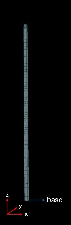
As you can see, here is my soil column model.
I am using 67 hexahedral solid elements with element type 1 (no rotation get recorded) on top of each other. I am fixing base in z direction.Â
I am constraining the nodes (CONSTRAINED_NODE_SET) at each elevation to have the same response in x, y, and z direction (except the nodes at the base which are constrained in x and y directions). I am doing so to have pure shear behavior (periodic boundary condition mentioned in the first reference you mentioned).
Then I apply PRESCRIBED_MOTION_SET as dispalcement to the nodes at the base.
When I check the acceleration response at the base nodes, I see considerable big numbers. And I am not getting what is wrong. The records at the other elevations look fine since I verified them using OpenSees.
Also, when I use velocity as my input motion, I do not see such problem. I am just looking for the reason that dispclement has such problem.
Â
Thanks
Mostafa
-
November 6, 2024 at 10:33 pm
Pedram Samadian
Ansys EmployeeHi Mostafa,
Thanks for the info. My first doubt is the unit consistency issue. Please first check whether the input value for the velocity is consistent with the unit system you used in the model.
If the units are consistent, please verify again whether your input velocity-time curve reproduces the same displacement curve input in your other model.
My next doubt is related to manual time scaling in the simulation (i.e. scaling the time down by a factor and correspondingly scaling up or down other time-dependent variables in the simulation like velocity and strain rate). In case you used a time scaling appraoch, please check you properly scaled parameters.
Please keep me posted.
Thanks,
Pedram
-
November 7, 2024 at 8:21 pm
mostafam
SubscriberHello Pedram
I am sure about the consitency of my units so I don't think the problem comes from there.
Also, I am not using any time scaling approach.
About the second source of error you mentioned, honestly I did not understand it well. Could you please elaborate it for me a little bit?
Thanks
Mostafa
-
November 8, 2024 at 10:05 pm
Pedram Samadian
Ansys EmployeeHi Mostafa,
No problem. You had mentioned that you do not face such an issue when you input a velocity curve. What I asked is to please verify your input displacement curve (dL vs. time) in the "bad" model is consistent with your input velocity curve (V vs. time) in the "good" model? Basically, you need to obtain a displacement curve from your velocity curve in the "good " model and compare it with your input displacement curve in the "bad" model.
I hope I could clarify it.Thanks.
Pedram
-
- You must be logged in to reply to this topic.
- LS-DYNA Installation Issues with Student Workbench 2024 R2
- Cross-coupled stiffness elements in LS-DYNA
- Initial Velocity Generation
- MAT072R3- concrete damage rel3 validation
- Initial Stress Shell Application and HistVarCosine in LS-DYNA
- shape memory alloy material in LS-DYNA
- *** Error 40058 (SOL+58) retractor 1000002:convergence failure at time1.01E+02
- LS-Dyna, Negative volume problem.
- Mohr_Coulomb material model (MAT_173)
- Johnson-Cook material strength model and the Johnson-Cook fracture model.
-
1987
-
896
-
599
-
591
-
398
© 2025 Copyright ANSYS, Inc. All rights reserved.