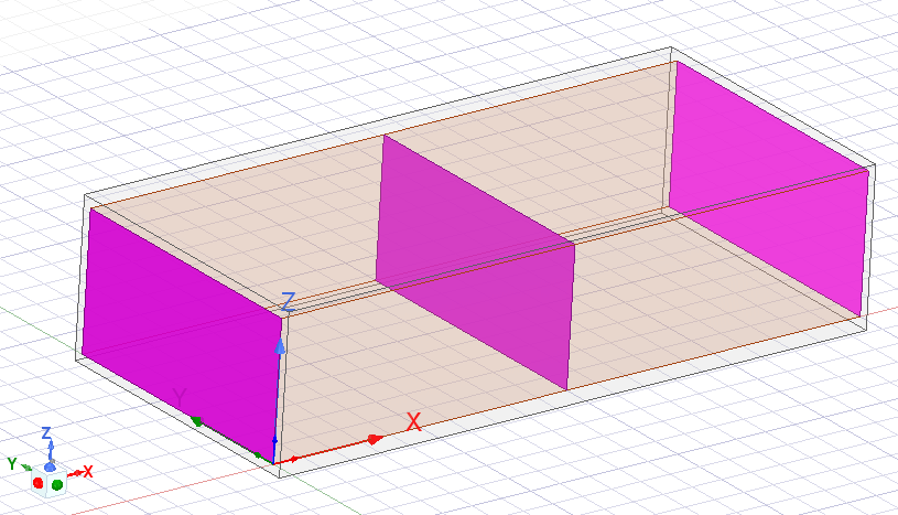
I am trying to use HFSS to give an example to my students about poynting vector. The model I am simulating is a simple rectangular waveguide (WR340) of 20 cm long and with an input signal of 2.45 GHz and 1 W. On both sides a wave port is assigned. The poynting vector is calculated in a non-model surface in both ports and in the middle of the waveguide as seen in the image.
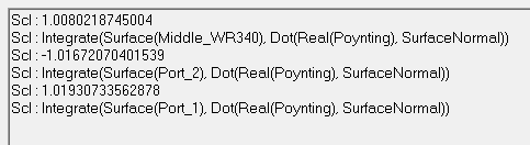
The poynting vector has been calculated using fields calculator tool by selecting the real poynting vector and integrating it on a selected surface. With an input signal of 1 W and ports on both sides, the value of the power through each surface should be exactly 1 W (or a bit less because of losses). However, the evaluated power is 1.019 W on the input port, 1.017 W on the output port and 1.008 W on the middle of the waveguide.
So I would appreciate if someone could with a me hint why this happens. Thank you all.


