Hello Chandra,
thank you for your helpfull answer.
When I apply the changes the plot isn’t still what I indended.
Here is my applied script:
/graphics,power
/post1
step_nr=5
!
set,step_nr
*stat
esel,s,type,,mycid !
! set colors for white background
/RGB, INDEX,100,100,100, 0
/RGB, INDEX,80,80,80, 13
/RGB, INDEX,60,60,60, 14
/RGB, INDEX,0,0,0, 0
!
/show,png
/trlcy,cm,0,bed
/trlcy,cm,0,bed2
/trlcy,cm,1,path
esel,s,ename,173
/trlcy,elem,0
esel,all
!
/view,all,1,1,1
/angle,1,0,ZM,0
/angle,2,0,ZM,0
/eshape,1
ples,cont,flux ! plot heat flux through contact elements
etable,tcc_i,nmisc,94
!
plet,tcc_i,1
allsel
!
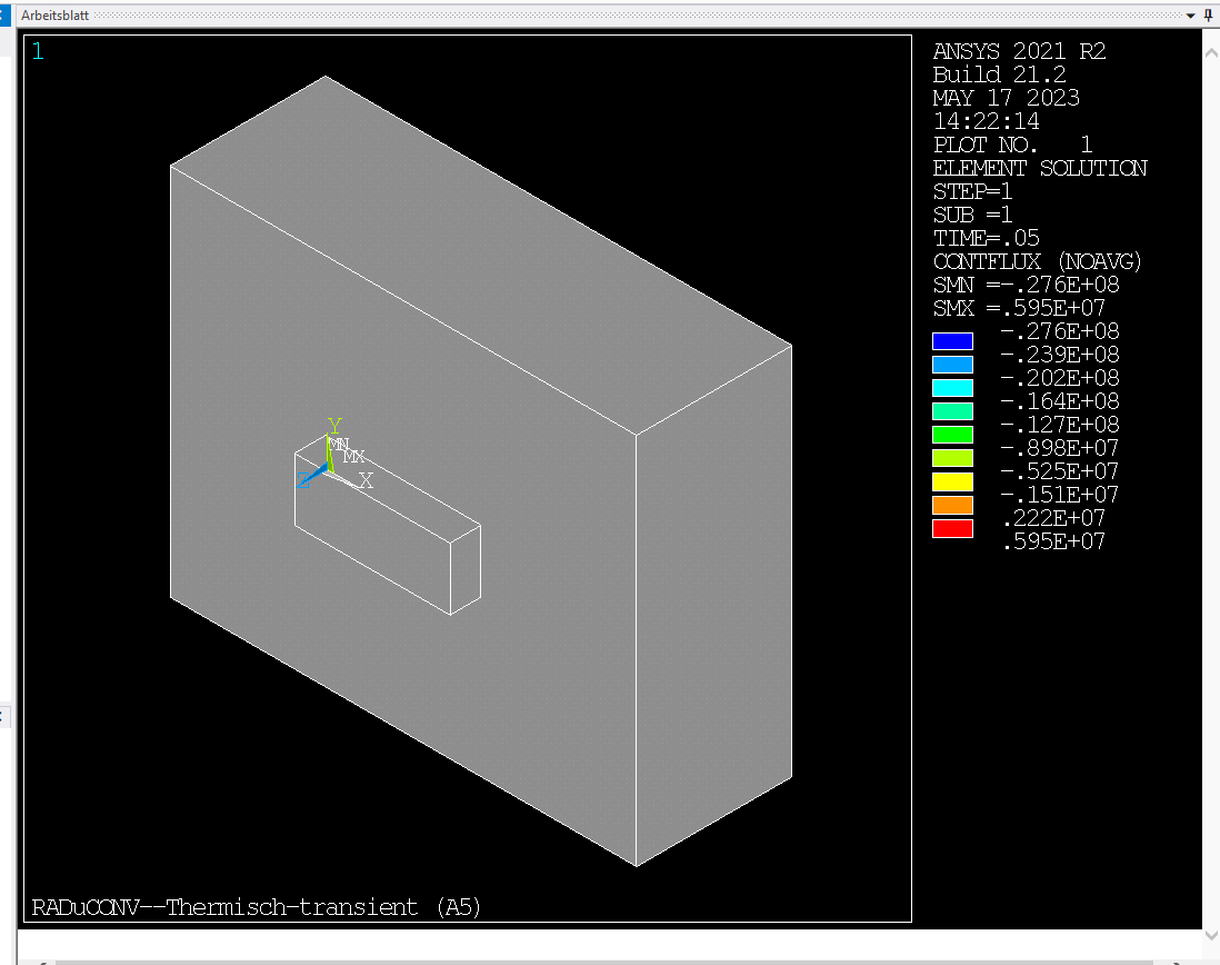
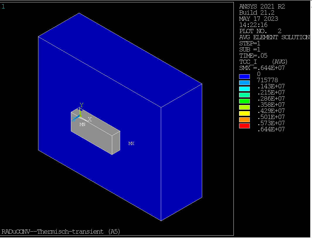
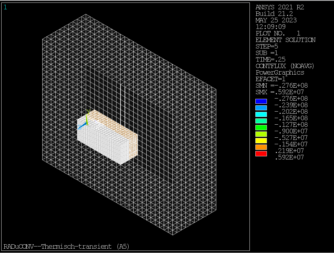
! plot 1 = thermal flux at the contact surface
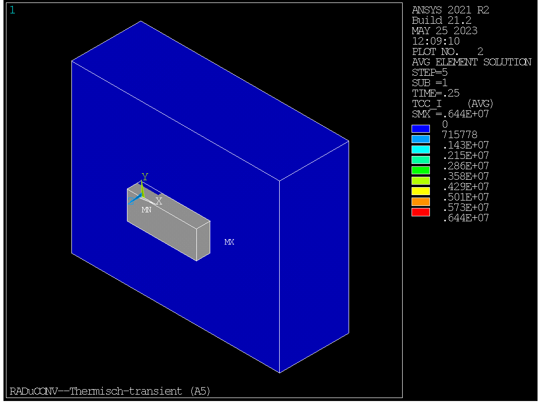
! plot 2 = applied thermal contact conductance
The plots are looking this way:
The solve out file shows this:
***** ANSYS RESULTS INTERPRETATION (POST1) *****
*** NOTE *** CP = 413.531 TIME= 13:48:38
Reading results into the database (SET command) will update the current
displacement and force boundary conditions in the database with the
values from the results file for that load set. Note that any
subsequent solutions will use these values unless action is taken to
either SAVE the current values or not overwrite them (/EXIT,NOSAVE).
PARAMETER ARG1 = 5.000000000
Use PowerGraphics for solid and shell elements
*** NOTE *** CP = 413.531 TIME= 13:48:38
Facet level set to 1 for maximum speed
Use /EFACET,2 for curved boundaries.
You have already entered the general postprocessor (POST1).
PARAMETER STEP_NR = 5.000000000
USE LOAD STEP 5 SUBSTEP LAST FOR LOAD CASE 0
SET COMMAND GOT LOAD STEP= 5 SUBSTEP= 1 CUMULATIVE ITERATION= 5
TIME/FREQUENCY= 0.25000
TITLE= RADuCONV--Thermisch-transient (A5)
ABBREVIATION STATUS-
ABBREV STRING
SAVE_DB SAVE
RESUM_DB RESUME
QUIT Fnc_/EXIT
POWRGRPH Fnc_/GRAPHICS
PARAMETER STATUS- ( 84 PARAMETERS DEFINED)
(INCLUDING 24 INTERNAL PARAMETERS)
NAME VALUE TYPE DIMENSIONS
ABC -1.00000000 SCALAR
AX 5.000000000E-004 SCALAR
BX 0.00000000 SCALAR
CID 7.00000000 SCALAR
DT 5.000000000E-002 SCALAR
DTCOOL 0.100000000 SCALAR
DY 5.000000000E-004 SCALAR
DZ 5.000000000E-004 SCALAR
HC_A 100.000000 SCALAR
HC_B 80.0000000 SCALAR
HC_C 60.0000000 SCALAR
HC_EX_COOL 30.0000000 SCALAR
HC_OUT 30.0000000 SCALAR
I 20.0000000 SCALAR
ICOOL 1.00000000 SCALAR
II 1.00000000 SCALAR
IIJJ 2.00000000 SCALAR
IJK 2.00000000 SCALAR
J 1.00000000 SCALAR
JJJ 1.00000000 SCALAR
KK 20.0000000 SCALAR
LC 1.00000000 SCALAR
PC 1.00000000 SCALAR
PDY 1.000000000E-003 SCALAR
SC 1.00000000 SCALAR
STEP_NR 5.00000000 SCALAR
T 1.00000000 SCALAR
TA 80.0000000 SCALAR
TB 60.0000000 SCALAR
TBED 40.0000000 SCALAR
TBULK 25.0000000 SCALAR
TC 50.0000000 SCALAR
TCC2 TABLE 2 1 1
TEMPERATURE TEMP CHARACTER
TEX_COOL 40.0000000 SCALAR
THXY1 0.00000000 SCALAR
THXY2 0.00000000 SCALAR
THYZ1 0.00000000 SCALAR
THYZ2 0.00000000 SCALAR
THZX1 0.00000000 SCALAR
THZX2 0.00000000 SCALAR
TID 8.00000000 SCALAR
TL 70.0000000 SCALAR
TOL 1.000000000E-006 SCALAR
TOUT 10.0000000 SCALAR
TR 0.100000000 SCALAR
VX 1.000000000E-002 SCALAR
XLOAD 5.000000000E-004 SCALAR
XR1 1.000000000E-002 SCALAR
XR2 8.000000000E-003 SCALAR
X_BOX_B 5.000000000E-004 SCALAR
X_BOX_C 5.000000000E-004 SCALAR
YCORR 1.000000000E-003 SCALAR
YLOAD 5.000000000E-004 SCALAR
YR1 1.500000000E-003 SCALAR
YR2 1.500000000E-003 SCALAR
Y_BOX_B 5.000000000E-004 SCALAR
Y_BOX_C 5.000000000E-004 SCALAR
ZR1 5.000000000E-004 SCALAR
ZR2 5.000000000E-004 SCALAR
PARAMETER PRIMARY VARIABLE LISTING-
NAME VARIABLE(S)
TCC2 1=TEMP 2= 3=
*** WARNING *** CP = 413.969 TIME= 13:48:39
Specified range of 0 to 0 is not permitted. The ESEL command is
ignored.
RED=100% GREEN=100% BLUE=100%
for color index 0.
RED=80% GREEN=80% BLUE=80%
for color index 13.
RED=60% GREEN=60% BLUE=60%
for color index 14.
RED=0% GREEN=0% BLUE=0%
for color index 0.
/SHOW SWITCH PLOTS TO PNG - RASTER MODE.
COMPONENT BED TRANSLUCENCY SET TO 0.0000
COMPONENT BED2 TRANSLUCENCY SET TO 0.0000
COMPONENT PATH TRANSLUCENCY SET TO 1.0000
*** WARNING *** CP = 414.016 TIME= 13:48:39
For item = ENAME, component = 173 is invalid. The ESEL command is
ignored.
ALL ELEM TRANSLUCENCY SET TO 0.0000
ALL SELECT FOR ITEM=ELEM COMPONENT=
IN RANGE 1 TO 99718 STEP 1
84182 ELEMENTS (OF 84182 DEFINED) SELECTED BY ESEL COMMAND.
view point for window 1 1.0000 1.0000 1.0000
ROTATION ANGLE FOR WINDOW 1 IS 0.00 ABOUT AXIS ZM
ROTATION ANGLE FOR WINDOW 2 IS 0.00 ABOUT AXIS ZM
ELEMENT DISPLAYS USING REAL CONSTANT OR SECTION DATA WITH FACTOR 1.00
DISPLAY ELEMENT SOLUTION, ITEM=CONT COMP=FLUX
CUMULATIVE DISPLAY NUMBER 1 WRITTEN TO FILE file000.png - RASTER MODE.
DISPLAY TITLE=
RADuCONV--Thermisch-transient (A5)
STORE TCC_I FROM ITEM=NMIS COMP= 94 FOR ALL SELECTED ELEMENTS
*** WARNING *** CP = 415.156 TIME= 13:48:39
The ETABLE command has requested item = NMISC, comp = 94 of element 1
(element type SOLID279). 0.0 is output, as this item does not exist.
Checking for this discontinues.
DISPLAY ELEMENT TABLE, ITEM=TCC_I OPER=1
*** NOTE ***
libpng version 1.0.8 - July 24, 2000
Copyright (c) 1998-2000 Glenn Randers-Pehrson
Copyright (c) 1996, 1997 Andreas Dilger
Copyright (c) 1995, 1996 Guy Eric Schalnat, Group 42, Inc.
ZLIB Version 1.2.11 Copyright (C) 1995-1998 Jean-loup Gailly and Mark Adler
CUMULATIVE DISPLAY NUMBER 2 WRITTEN TO FILE file001.png - RASTER MODE.
DISPLAY TITLE=
RADuCONV--Thermisch-transient (A5)
SELECT ALL ENTITIES OF TYPE= ALL AND BELOW
PARAMETER LOADSTEP = 1.000000000
You have already entered the general postprocessor (POST1).
USE LOAD STEP 1 SUBSTEP LAST FOR LOAD CASE 0
SET COMMAND GOT LOAD STEP= 1 SUBSTEP= 1 CUMULATIVE ITERATION= 1
TIME/FREQUENCY= 0.50000E-01
TITLE= RADuCONV--Thermisch-transient (A5)
*GET NUMNODE FROM NODE ITEM=COUN VALUE= 283054.000
SET PARAMETER DIMENSIONS ON NODETEMP
TYPE=ARRA DIMENSIONS= 283054 4 1
VECTOR GET OPERATION nodetemp(1,1) VECTOR LENGTH= 283054
NAME= NODE 1 LOC X
VECTOR GET OPERATION nodetemp(1,2) VECTOR LENGTH= 283054
NAME= NODE 1 LOC Y
VECTOR GET OPERATION nodetemp(1,3) VECTOR LENGTH= 283054
NAME= NODE 1 LOC Z
VECTOR GET OPERATION NodeTemp(1,4) VECTOR LENGTH= 283054
NAME= NODE 1 TEMP
OPENED FILE= myTempfileWF.txt FOR COMMAND FILE DATA
MAXIMUM TERM IN RESULT VECTOR= 1
STRIDE IN VECTOR OPERATION= 1
COMMAND FILE CLOSED
PARAMETER NODEID = 27844.00000
EXIT THE ANSYS POST1 DATABASE PROCESSOR
I’m only interested in the display of the contact 173 elements and the heat flux through these elements. But I can’t plot it this way. The grey part named “path” should be transparent but it’s not. The underlying “bed” and “bed2″ should be not transparent, this is right in the second plot.
With best regards
John M.