-
-
December 2, 2024 at 5:41 amsebastianhao11Subscriber
I am new to ANSYS software and currently self-learning. I am working on simulating fluid behavior during extrusion in a die using ANSYS Polyflow. I would appreciate your guidance on the following questions:
1. How can I set the outlet die pressure boundary condition to zero, as shown in Figure 1? I tried manually setting the fn/fs imposed at the boundary condition to zero along the die outlet, but it doesn’t seem to work.
2. Why does the pressure contour in Figure 2 look blocky instead of showing a smooth gradient transition? What could be the source of this issue, could it be a problem with the graphics settings? Additionally, the outlet pressure at the cylinder end appears negative instead of zero. What might be causing this discrepancy?
If there are any technical mistakes in my approach or understanding, I am open to your guidance and corrections. Thank you in advance for your time and assistance. I sincerely appreciate your advice! -
December 11, 2024 at 8:59 amPrashanthAnsys Employee
Hello, please find the answers to your questions..
-- First of all, the pressure variable (p) does not necessarily correspond to the pressure that could be experimentally measured with an appropriate device. The experimentally measured quantity corresponds actually to a given component of the force density applied to a given surface (with its normal vector).There is probably a historical reason for the confusion: for an incompressible Newtonian fluid in a simple Poiseuille flow, the calculated pressure corresponds to the one that could be measured. Notwithstanding, for a general complex flow, the pressure variable should at first be understood as the unknown (Lagrange multiplier) associated with the incompressibility constraint
To illustrate this, let us consider a simple extensional flow along the z-direction for a Newtonian fluid filament. We assume that a zero force is applied on the border. The total stress tensor S is diagonal, and given by:Szz = -p + 2 eta . e-dot , Sxx = Syy = -p - eta . e-dot ,where eta is the viscosity, while e-dot is the extension rate (positive). Since we assumed that a zero force is applied on the border of the filament, we have:p = -eta . e-dot
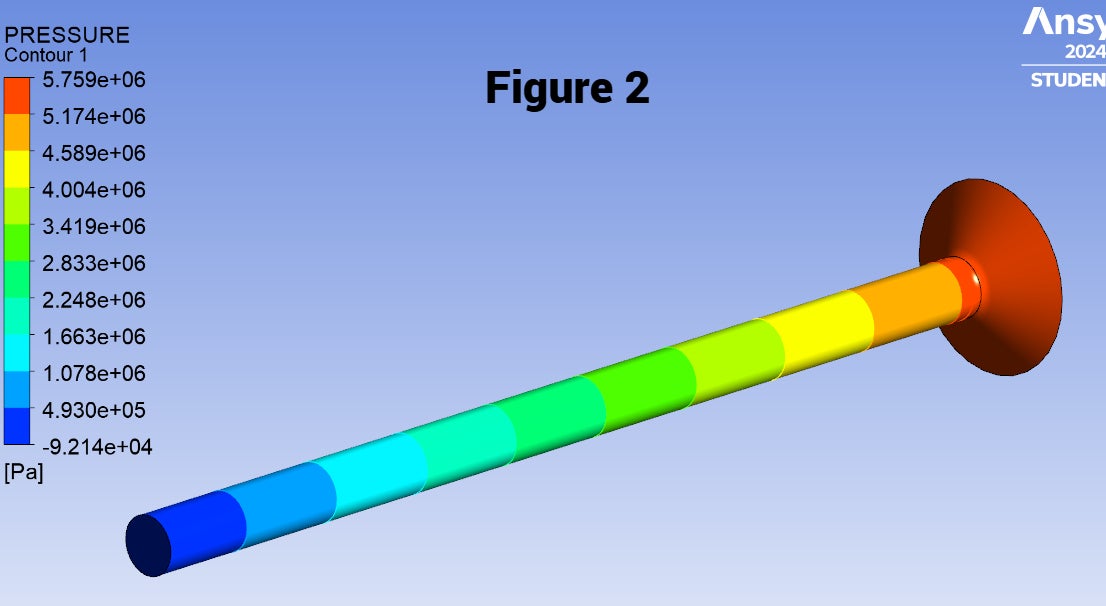
Hence, the pressure can be as negative as one wants.Â-- Yes, it looks blocky since you have defined only 11 color bands (by default). You can increase the # of contours to make it smooth.. -
December 17, 2024 at 1:10 pmsebastianhao11Subscriber
Thank you for your response. The graphical issue has been resolved. Regarding your answer to my other question, I will take some time to review and study it. I truly appreciate your help.
-
- You must be logged in to reply to this topic.
- How do I get my hands on Ansys Rocky DEM
- Non-Intersected faces found for matching interface periodic-walls
- Fluent fails with Intel MPI protocol on 2 nodes
- Unburnt Hydrocarbons contour in ANSYS FORTE for sector mesh
- Help: About the expression of turbulent viscosity in Realizable k-e model
- Cyclone (Stairmand) simulation using RSM
- Mass Conservation Issue in Methane Pyrolysis Shock Tube Simulation
- Script Error
- Facing trouble regarding setting up boundary conditions for SOEC Modeling
- convergence issue for transonic flow
-
1602
-
602
-
599
-
591
-
366
© 2025 Copyright ANSYS, Inc. All rights reserved.