Ansys Assistant will be unavailable on the Learning Forum starting January 30. An upgraded version is coming soon. We apologize for any inconvenience and appreciate your patience. Stay tuned for updates.
LS Dyna

LS Dyna

Topics related to LS-DYNA, Autodyn, Explicit STR and more.

Piezoelectric effect

TAGGED: 

    • dinhan0394
      Subscriber
      Dear all,
       
      I tried to perform a simple piezoelectric using LS-DYNA: a piezoelectric block with a fixed bottom surface and a pressure load on the top surface.
       
      I have referred to the results from some other examples, the voltage results are evenly distributed.
      As done in LS-DYNA, the results do not have such a distribution but are skewed as shown in Figure 2.
      - Reference:
       
      LS-DYNA result:
      Does anyone know how to fix this or have a simple example?
      Thanks
    • peteroznewman
      Subscriber

      To get a uniform voltage response across the body, I suggest you delete the Fixed Support and replace it with three displacements: X=0 on one face with an X-axis normal, Y=0 on one face with a Y-axis normal and Z=0 on one face with a Z-axis normal. In each displacement boundary condition, the other two displacements are left Free. This will allow the body to freely expand on the free sides due to Poisson's Ratio effect as the pressure compresses through the thickness.

      • dinhan0394
        Subscriber

        Dear peteroznewman,

        Thank you for your suggesstion. I tried it but the results are the same.

        Voltage result:

        When I active the piezo effect, all results look not good (it is always skewed in a certain position)

        Here is X-displacement (direction of force)

    • peteroznewman
      Subscriber

      The results are not the same, but I see it is not what you want.
      The voltage in your original post goes from   -66 to +25 volts.
      The voltage with the new boundaries is from -71 to +16 volts.

      Maybe someone else will have a suggestion.

    • ErKo
      Ansys Employee


      Hi 

      In the ABAQUS image – bottom is grounded – do the same in your model (ground -> volt=0).

      Finally I think in the ABAQUS model has pressure both on top and bottom

      In general it is hard to use the PZT as the anisotropic mat. properties are hard to set up.

      Alternatively:

      Easier in Mechanical – see this example in the ansys help manual:

      Chapter 39: Wire Bonding Ultrasonic Transducer


      All the best

      Erik


      • dinhan0394
        Subscriber

        Dear Erik

        Thanks for your suggestions.

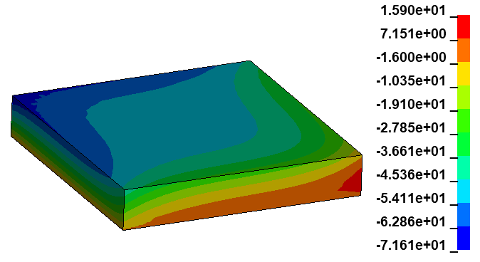
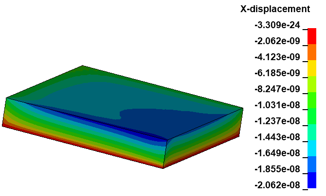
        I have solved this problem using Ansys Mechanical. Now I want to use LS-DYNA due to some technical requirements.

        As you said, the difficulty in this problem is related to the material definition. In LS-DYNA, the keyword MAT_ADD_PZELECTRIC is used to declare the piezo property but I did not understand the direction of the quantities in it clearly which leads to the error.

        Now I have a good solution after changing the values ​​of some parameters in that model but I did not really understand it clearly.

        If you can share any document to explain the material parameters, it would be very helpful.

        Thank you.

    • nishant.singh
      Subscriber

      Dear dinhan0394.

      May I know, how you are setting up the output to see voltage ?

    • dinhan0394
      Subscriber

      Hi nishant.singh 

      In this problem, Z-acceleration result is Voltage output.

Viewing 5 reply threads
  • You must be logged in to reply to this topic.
[bingo_chatbox]