-
-
September 7, 2023 at 2:45 pm
MonMon
SubscriberHello,
I hope you all are fine.
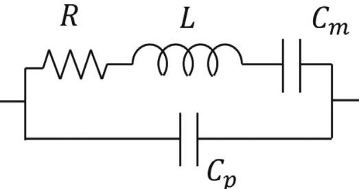
I took a long time to connect the equivalent circuit of the piezo material (Quartz) to its electrodes (attached on both sides of the quartz), gave it sine voltage, and did a harmonic analysis to see the amplitude of piezo oscillation in the specific range of frequency. I added the CAD data directly to the workbench and added the APDL commands (attached) to the modal analysis (added before the harmonic analysis). Based on the errors I receive " Element 18590 does not have all of its required nodes defined. The E command is aborted" I am guessing that the problem is with nodes and elements that I introduced. It would be really appreciated if you can help me with this issue.
I attached the equivalent circuit and the APDL codes, Thanks in advance for your help.
Â
cmsel, S, Base
nsle, S, All
et,1,SOLID226,1001
*get,Epz,elem,,count ! Get the number of solid elements
cmsel, S, POS
nsle, S, All
cp,1,volt,all
*get,POS,node,0,num,min ! get master node on bottom electrodecmsel, S, GND
nsle, S, All
cp,2,volt,all
*get,GND,node,0,num,min ! get master node on top electroded,GND,volt,0 ! ground bottom electrode
d,POS,volt,1
fini
/prep7
!
! Element types
!
et,62,CIRCU94,0 ! R1
et,63,CIRCU94,2 ! C1
et,64,CIRCU94,1 ! L1
et,65,CIRCU94,2 ! C0
et,66,CIRCU94,4 ! C0
!
! Real constants
!Vmax = 1
R1 = 22439.55
L1 = 6405.34626
C1 = 3.69e-14
C0 = 1.82e-12
r,1, Vmax
r,2, R1Â
r,3, L1Â
r,4, C1
r,5, C0! Nodes and elements
!
n,1,0,0
n,2,0,1
type,65 $ real, 5
e, 2, 1
type,66 $ real, 1
e, 1, 2 ! Voltage sourceÂ
e, POS, GND ! Voltage source feedingÂn,3,1,1/3
n,4,1,2/3type,62 $ real, 2Â
e, 1, 3
type,64 $ real, 3
e, 3, 4
type,63 $ real, 4
e, 4, 2
fini -
September 8, 2023 at 2:30 pm
Erik Kostson
Ansys EmployeeÂ
Â
Yes, the nodes 1,2,3,4 allready exists in the workbench mesh/model so can not be used again (find the last node number and add 1 and use that in the new nodes).
You can see in VM237 how to use circu94 with solid226 piezo – in there you will see that he pzt starts from node10 (
Â
NUMSTR,NODE,10),
Â
then it is ok to define N,1 and so on since these nodes do not exist.
Also look for posts in the forum (e.g., : /forum/forums/topic/ansys-2021-workbench-piezoelectric-analysis-add-resistor/)
All the best
Erik
Â
Â
-
September 8, 2023 at 3:17 pm
wrbulat
Ansys EmployeeAs an alternative to Erik's suggestion, you can interrogate the MAPDL database for the highest numbered node that exists in the model. Let's call it NMAX. This command:
*get,NMAX,node,,num,max
will define parameter NMAX and set its value to the highest numbered node in the model. You can then create additional nodes to construct the CIRCU94 elements:
n,NMAX+1,xlocation,ylocation,zlocation
n,NMAX+2,xlocation,ylocation,zlocation
By the way, APDL is not case sensitive.
Â
Kind regards,
Bill
-
- The topic ‘Piezo-Circuit, how to add the APDL code in work bench’ is closed to new replies.
- The legend values are not changing.
- LPBF Simulation of dissimilar materials in ANSYS mechanical (Thermal Transient)
- Convergence error in modal analysis
- APDL, memory, solid
- How to model a bimodular material in Mechanical
- Meaning of the error
- Simulate a fan on the end of shaft
- Nonlinear load cases combinations
- Real Life Example of a non-symmetric eigenvalue problem
- How can the results of Pressures and Motions for all elements be obtained?
-
3862
-
1414
-
1241
-
1118
-
1015
© 2025 Copyright ANSYS, Inc. All rights reserved.