

-
-
November 9, 2021 at 7:13 pm
HumbertoSantos
SubscriberDear all
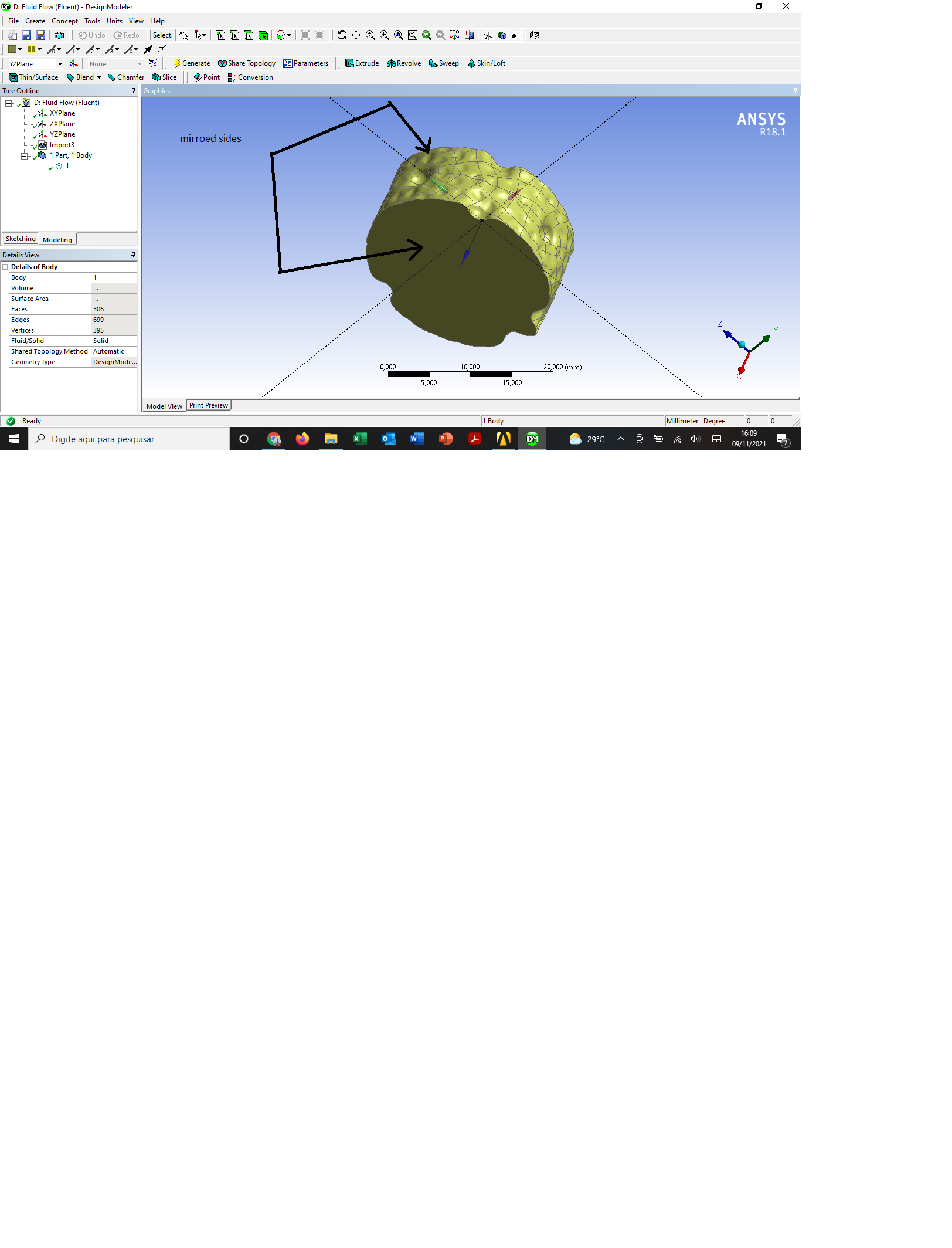
I am setting up a simulation of a complex tube geometry, dimpled tube. Since the actual length would require computar capabilities not available, I decided to run periodic analysis. However, everytime when I try to create the periodic zones, the following message appears:
warning: number of elements does not match between zone 6 and 7.
error: failed to make zones periodic.
error object: #f
I am sure that both opposite sides of the tube (inlet and outlet) are identical. I say this because they are mirroed sides. Yet, I still get this message. I have changed multiple parameters but still get the same error.
I have also read many post here, on cfd.com and researchgate. I have even tried face matching control. No success.
Any clue on what should I do or extra material that I could read and get a possible solution for this?
I have attached an image of my geometry.
Thanks in advance
November 10, 2021 at 11:33 amRob
Forum ModeratorHow did you mirror the mesh? Periodic boundaries need an exact node/facet alignment so if you didn't force this it often fails. However, if you ensure you have two separate labels and turn them to interface you can create a nonconformal periodic via the Mesh Interface panel.
November 10, 2021 at 2:56 pmSubscriberHi, Rob.
Thanks for your reply.
I used the mirror tool from DM. First I got half of the tub with the repeating geometry, and then I used the xy plane to mirror.
Is this non-conformal technique the window enabled when I select the inlet, for example, as interface within boundary conditions ? Or should it be done in the meshing ?
November 10, 2021 at 4:59 pmForum ModeratorYou've mirrored the geometry, that doesn't mean the mesh is the same. The non-conformals use the surfaces you pick (define) as "interface" in Fluent, you then create the "interface pair". It's simple when you know how. Unfortunately in the current release the "assistant" isn't working quite right, so it needs turning off, https://ansyshelp.ansys.com/account/Secured?returnurl=/Views/Secured/corp/v212/en/flu_ug/flu_ug_sec_nonconform_using.html
Then use Mesh Interfaces from the tree (left side menu) to create the pair. Read any prompts carefully.
November 11, 2021 at 5:49 pmSubscriber
Hi Rob,
Thank you once again.
I use Fluent 2018. I guess it is a little different and do not need turning off the assistant . Am I correct?
I followed the steps below. I have attached the screenshots for each step.
1 ÔÇô Chose inlet and outlet as interface;
2 ÔÇô After step one, an option named ÔÇ£Mesh InterfaceÔÇØ appeared below boundary condition and is as follows.Then I clicked on ÔÇÿManual Create..ÔÇÖ with both inlet and outlet selected.
3 ÔÇô In the next window, I named the Mesh interface and under the Interface Zones Sides 1 an 2 I selected inlet and outlet, respectively. Then I chose periodic boundary conditions option and unmarked the auto compute offset. To finish, I clicked on create.
4- Now there are the options interface1-periodic, interface1-side1-wall-inlet (set as wall) and interface2-side2-wall-outlet (as wall).
5 ÔÇô Then I set the periodic conditions as usual. Mass flow rate = 0.0122 kg/s and upstream bulk temperature =335 K. For the heating wall boundary condition, I set a value of 5545 W/m^2.
6- I proceed with initialize and get the error:
Error: Non-conformal periodic interface with empty intersection.
This is likely due to incorrect specification of periodic
offset values. Please check the offset values specified
and recreate the interface.
Error: Couldn't intersect threads 7 and 6.
Error: Couldn't intersect threads 7 and 6.\n
Error Object: #f
From my point of view, there should not be any offset value (that is why I let them as 0 in x, y and z ÔÇô in screenshot 3) since the side of my model is located on the plane xy. Threads 7 and 7 are inlet and outlet, which are now interfaces.
Any comments are greatly appreciated.
November 12, 2021 at 12:20 pmForum ModeratorI'm not permitted to open attachments (check Rules for why), but you do need an offset for translational periodics. Otherwise the solver doesn't know how long the modelled section is (Fluent knows the cell sizes etc but the solver can't see a distance between two surfaces).
November 12, 2021 at 2:42 pmSubscriberIt is working now.
The problem was that I thought I only needed the periodic boundaries condition. But after create the mesh interface, the zones created must be treated as conventional (not periodic) boundaries. I changed the inlet and outlet interface zones to inlet mass flowr ate and outlet pressure, respectively, and set the values.
Problem solved.
Thanks a lot Rob.
November 12, 2021 at 4:16 pmForum ModeratorIt'll work, but that's not a periodic model.
November 23, 2021 at 4:08 pmSubscriberHi Rob, thanks and I have fixed it. I am not sure what was wrong after that, but it is working fine now.
Viewing 8 reply threads- The topic ‘Periodic boundary conditions error message in Fuent’ is closed to new replies.
Innovation Space Trending discussions
 Top Contributors
-
peteroznewman
 6625
6625 -
scabo
 1906
1906 -
Dennis Chen
 1469
1469 -
javat33489
 1311
1311 -
Shyam Prasad V Atri
1022
Top Rated Tags
© 2026 Copyright ANSYS, Inc. All rights reserved.
Ansys does not support the usage of unauthorized Ansys software. Please visit www.ansys.com to obtain an official distribution.
-
Ansys Assistant will be unavailable on the Learning Forum starting January 30. An upgraded version is coming soon. We apologize for any inconvenience and appreciate your patience. Stay tuned for updates.


