TAGGED: 2d-axisymmetric, fluent, microfluidic
-
-
April 16, 2024 at 11:49 pm
Teun Vandermeulen
SubscriberHello,
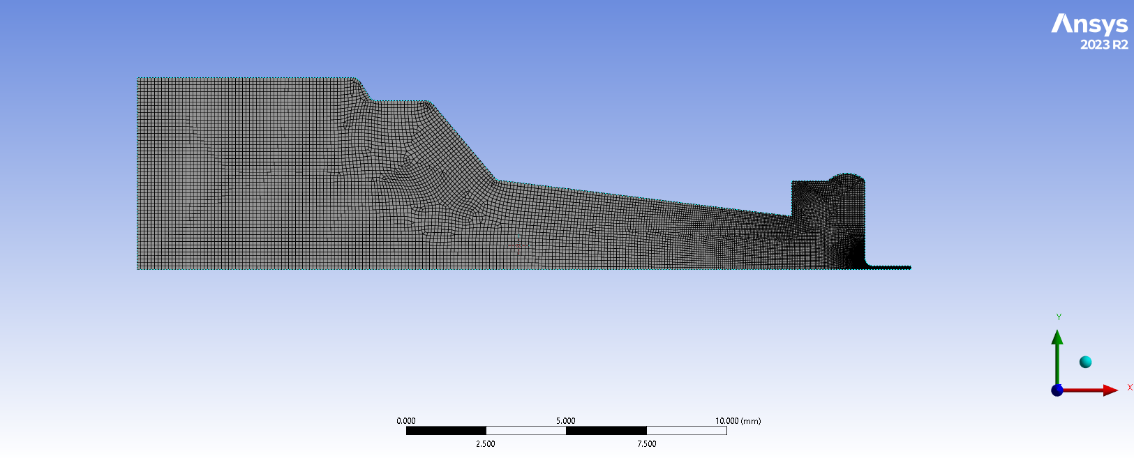
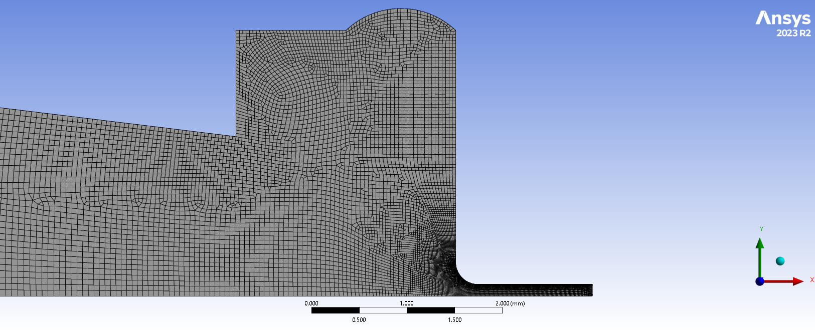
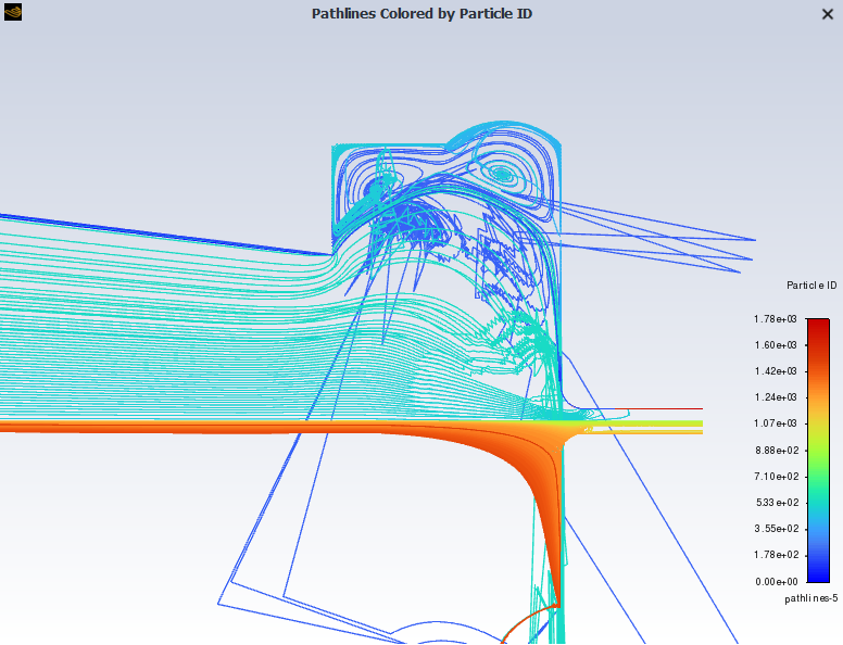
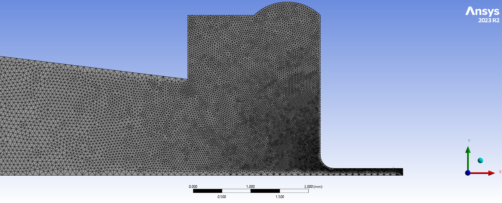
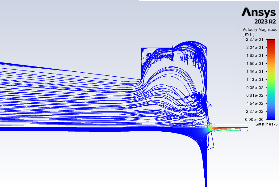
I'm modelling a 2D microfluidic device that represents a nozzle with a needle that will be used for bio-printing. I designed an axisymmetric model and created a fine mesh (good values for orthogonal quality and aspect ratio, see images 1&2). However, when I want analyze the flow behaviour through the device, the pathlines seem to 'escape' the model and errors increase (see image 3).
I have no idea what I'm doing wrong. I've adjusted the mesh multiple times, used different solution methods (SIMPLEC seems to work best), tried to re-build the geometry... But I bump into the same problem over and over again. I'm using an axisymmetric 2D space, and the BC are velocity inlet (on the left), pressure outlet (on the right), no-slip walls (top edges), and axisymmetric axis (lower edge). I get no errors when modelling the simulation.
What am I doing wrong? Please note that the needle (the outlet) is shortened, and is much longer in the real design.
-
April 17, 2024 at 9:27 am
Rob
Forum ModeratorPlease can you plot a velocity contour?
-
April 17, 2024 at 11:20 pm
-
April 18, 2024 at 9:11 am
Rob
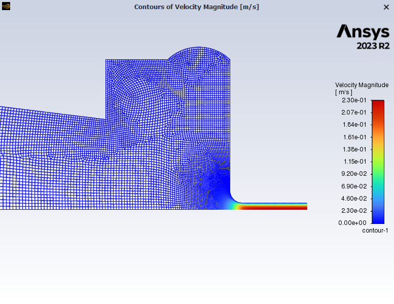
Forum ModeratorIf you don't pick anything in the surfaces list on the contour panel in 2d you'll get a better picture.
Thanks. Whilst you are interested in the pathlines tracing problems usually requires more/other information. Pathlines doing that are usually associated with very skew cells or underesolved velocity gradients, I can't see either in this case although the problems do seem to be related to the slightly odd cells between blocks of mostly map mesh. Zoom in & replot velocity for the "blue" contour band range and node values off.
-
April 22, 2024 at 11:49 pm
Teun Vandermeulen
SubscriberHi,
Thanks for your reply. I,ve added an image of the velocity contour plot, which looks fine and as expected. Regarding the pathlines, I tried a totally different meshing method (hydrodynamic meshing) to see what it does (see second image, mesh not optimilazied though). This seems to give the exact same problem, with the pathlines failing at the same point (see image 3). This looks very strange to me. Could it be something else than the mesh causing this?
Thanks
-
April 23, 2024 at 8:38 am
Rob
Forum ModeratorWell, you do need to fix the mesh (again) - look at the near wall resolution. Can you replot the velocity between about 0 and 0.01, you may need to look at contours and vectors.
-
- The topic ‘Pathlines fail to establish and escape’ is closed to new replies.


-
3467
-
1057
-
1051
-
929
-
896

© 2025 Copyright ANSYS, Inc. All rights reserved.

