Hi all!
I'm currently working through a university project that requires us to analyse a thin plate (SHELL281 elements) fixed at its edges with a pressure applied on the plate:
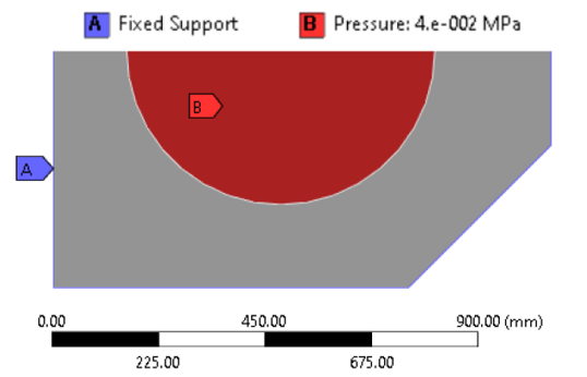
(Note that a symmetry has been applied on the longest edge in the diagram shown above)
We are performing linear analysis (elastic material) with large deflections. The latter stages of the project require us to:
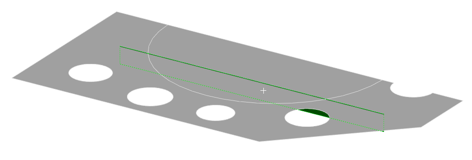
1. Add simple stiffeners to the underside of the plate
2. Add circular cutouts in the plate's face.
The aim is to minimise deflection (hence the stiffeners) while also minimising weight (hence the holes), all while ensuring max equivelant stress doesn't exceed a certain amount. The best optimisation strategy would therefore be to parametrise the position and sizing of the stiffeners and holes and apply upper bounds to the max stress and deflection. The problem that we're running into, however, is that the stiffeners cause stress singularities.
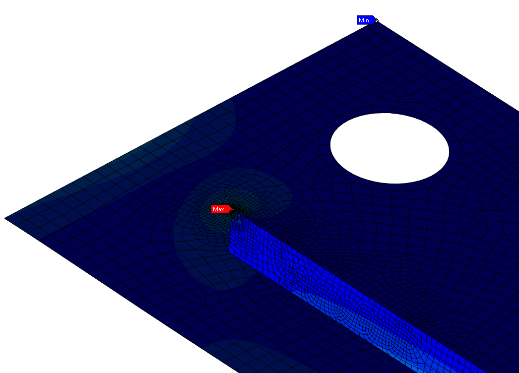
This means that targeting the maximum stress during optimisation is no longer possible, as the singularity 'steals' the maximum stress reading in the Mechanical solution. We also can't manually add a stress probe at a position and make the optimisation target that reading, because the changing geometry of the stiffener and the holes will shift the 'true' value of maximum stress to different locations for each run.
What we are looking for is a way to make Mechanical ignore the area surrounding the stress singularities, so that the maximum stress probe, which is capable of automatically moving itself each run, can be used as a target for our optimisation to make sure stress doesn't exceed a certain amount. Please note that identifying stress singularities and mitigating their effects is a component of this project, so we cannot remove the singularity from the model by, for example, adding a fillet.
Thank you very much for any insight people can provide.


