-
-
September 25, 2024 at 12:44 pm
aagalvez
SubscriberHello to everyone. I was trying to append case files of my three computational domains
Inlet domain, rotor domain, and outlet domain
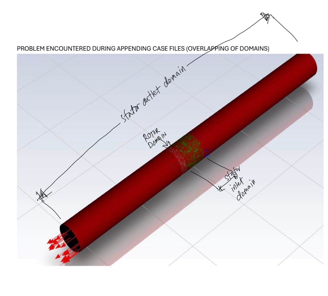
(mesh independently - non conformal mesh) but overlapping occured. Please see attached photo. I am first timer of appending case files and I dont know how to resolve this. I appeciate all your help. Thank you so much.

-
September 25, 2024 at 12:51 pm
Rob
Forum ModeratorThe append function simply drops the section of mesh into the domain at the position it was created for. Chances are it's overlapping because you didn't leave a gap between the inlet & outlet domain, or more likely didn't split the rotor section out of the inlet domain if that's the one it's colliding with.
Assuming you read in inlet, outlet and rotor in that order. Open inlet & transform by whatever distance is needed (ie how long the rotor is). Append the outlet. Hopefully there's a gap to fill when you import the rotor.
However, if you create a conformal geometry you could just mesh it all in one go. The interior faces between zones would be interior and could be slit if required to allow the rotor to actually move.
-
September 25, 2024 at 12:59 pm
aagalvez
SubscriberThank you for your comment sir Rob. Are you suggesting that I will leave exact distance/length for each domain in my geometry and then mesh it one domain at a time and append each after?
-
September 25, 2024 at 1:22 pm
Rob
Forum ModeratorOr all in one go. Both options are valid. Your method is one we used years ago when the computers couldn’t handle the zone cell count.
Have a look at the various meshing tutorials in Help.
-
September 25, 2024 at 1:46 pm
aagalvez
SubscriberThank you very much for your help, sir.
i am trying to replicate the meshing (mesh 1) and it turns out that in my mesh(mesh 2), when i mesh it all the domain at once, the interfaces doesnt look the same with that in mesh 1. Also, mesh 2 generates more cells compared to mesh 1. Will there be a problem with that? I am planning to validate some results on the solution of mesh 1 with my solution soon using my meshing (mesh 2). Thank you so much for your help.
-
September 25, 2024 at 2:14 pm
Rob
Forum ModeratorI'd move the interface a bit further away from the blades - why would you refine the mesh between blade and interface for no overall benefit? Look at the nonconformal guidelines in Help (or on here/Learning) for recommended size change limits.
Check the boundary setting in the second mesh - have you defined the interface as wall & inflated it? Then check all local size settings.
-
September 25, 2024 at 10:09 pm
aagalvez
SubscriberThank you for your suggestions sir.
-
September 28, 2024 at 11:22 am
aagalvez
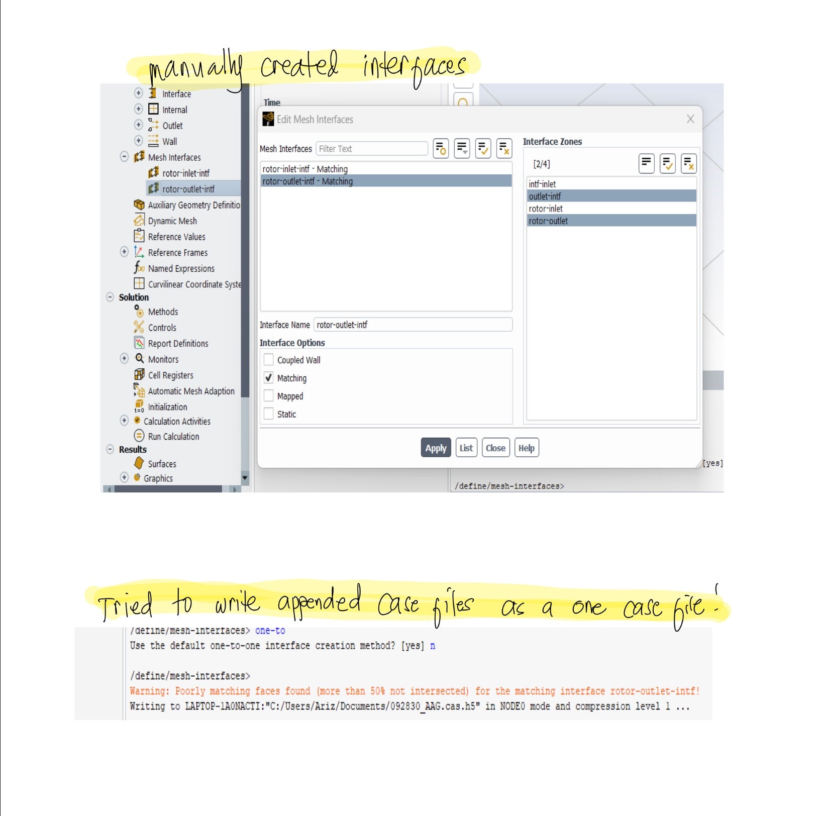
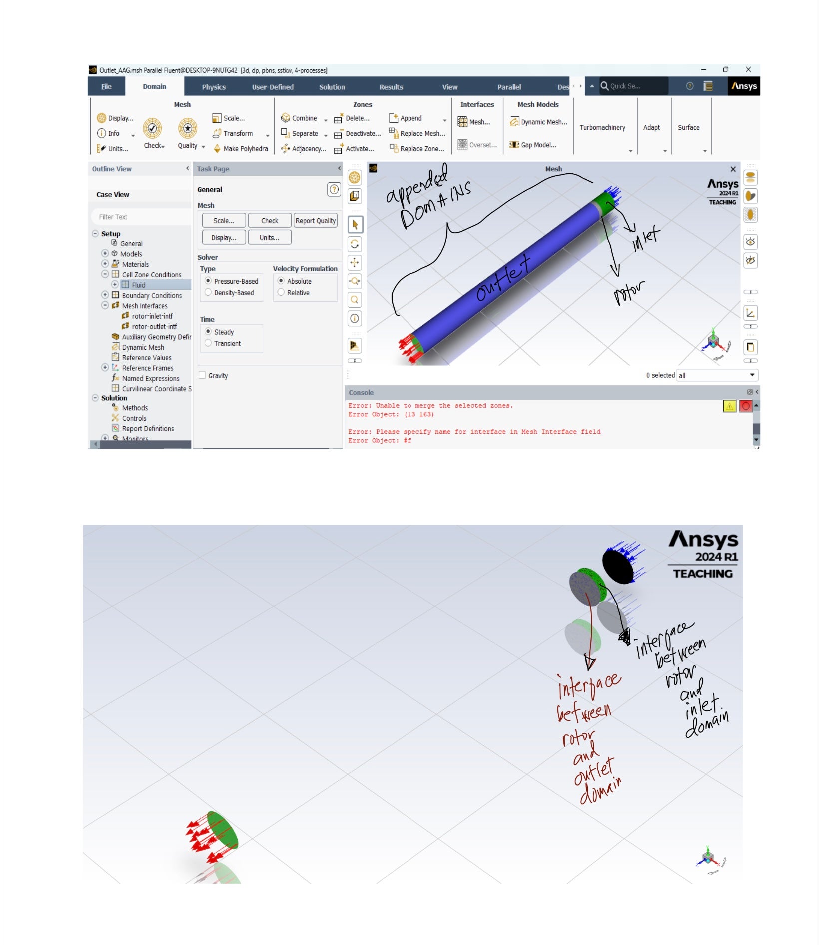
SubscriberHello, good evening to everyone. Here is an update of case files being appended. I provided some gaps between domains (inlet, rotor, outlet) and came up with this (first picture). My problem now is the creation of mesh interfaces between domains. I tried to manually create mesh interface between the domains but zi am not sure if it is correct. If it is correct, can I proceed already to setup? Thank you very much. Also, I encountered a warning when I tried to write it as one case file in my solution.

-
September 28, 2024 at 11:24 am
-
September 30, 2024 at 2:20 pm
Petros
Ansys EmployeeIt seems like the interface pair is not matching exactly one another, probably due to incorrect location of the domains. As suggested above it would be better to create the whole domain at once and split it before and after the rotor so then you have your 3 domains which you can import in one go.
-
October 1, 2024 at 3:46 am
aagalvez
SubscriberHello. Thank you for your comment. I tried to do the meshing as one but I am having a problem on my outlet domain since I want to set 4 number of boundary layers only on it and the other domains to be 8. Is it possible to varry the number of boundary layers in each domains?
-
October 1, 2024 at 12:09 pm
Rob
Forum ModeratorIt is, but that'll also cause issues at the interface.
-
- You must be logged in to reply to this topic.


-
3367
-
1050
-
1047
-
886
-
831

© 2025 Copyright ANSYS, Inc. All rights reserved.


