General Mechanical

General Mechanical

Topics related to Mechanical Enterprise, Motion, Additive Print and more.

Orientation of the layer application for curved surfaces in acp (pre)

    • katneckk
      Subscriber

      I have a curved surface with two holes. These holes are applied as ellipses. In the final printed part, these holes should point in the Z-direction.

      The fiber orientation of the laminates should follow the curved surface. How can I now specify that the application of the layers does not follow the curved surface, but a certain coordinate direction (such as the Z-direction)? Unfortunately, when I specify the direction as Z-direction (0,0,1) in the Oriented Selection Sets, it is oriented to the respective element orientation and not to the global Z-orientation. This means that my holes in ACP do not point in Z-direction but go 90° from the surface in an oblique direction. Do i have to specify some special reference direction rules?

      I hope you can understand my problem a little bit.

    • katneckk
      Subscriber
      Something like an option where you define if there should be vector offsetting or surface offsetting of the laminates.
    • Sean Harvey
      Ansys Employee
      Hello @katneckk I was trying to confirm what you are trying to do. Here I have a curved laminate and the hole edge follows global z using the extrusion guide vector on the solid model. Please see image below. If this is what you are trying to do, great. You just need to create a named selection in Mechanical that references the edge of the hole. That then comes into ACP as an edge set which you can reference in the below dialog box and there you specify the vector angle. You have to toggle the extrusion guide type to Direction to specify the vector.

      Let us know if this is what you are looking for. Thank you!
      Regards Sean

    • katneckk
      Subscriber
      Thanks for the answer. The ExtrusionsGuide is a step in the right direction. I have an L-shaped component which I want to extrude not only at the holes but all around the edges in the Z-direction. If I now create an ExtrusionGuide for all edges individually, my new solid model will become a deformed part. Also the error message "Solid model has some upside down element(s)" appears. Do I need to change any other settings, such as changing the Mesh Morphing Parameters?
      The first image is before Extrusion Guide, the second with Extrusion Guide but deformed and the third image is how the part should actually look (green).

    • Sean Harvey
      Ansys Employee

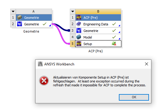
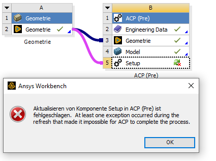
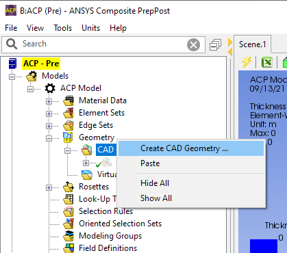
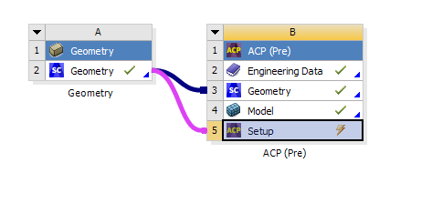
      Thanks for sharing the details. So, what I did was instead of using the vector direction, I pass the cad geometry into ACP.
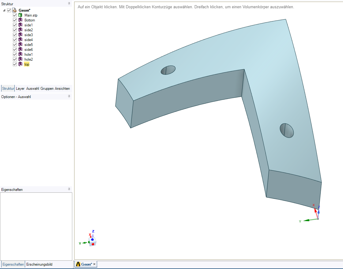
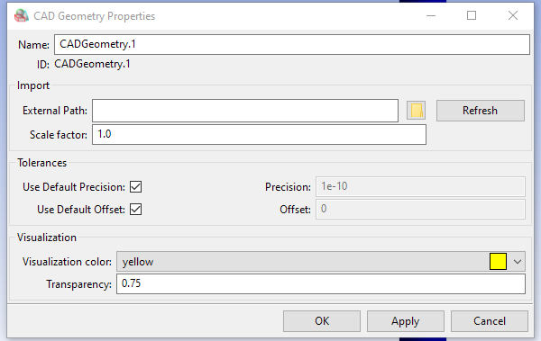
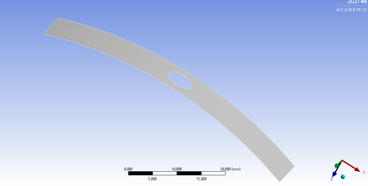
      I extract surfaces of each of the faces in SpaceClaim by selecting each surface, then ctrl-C, ctrl-V. and repeat
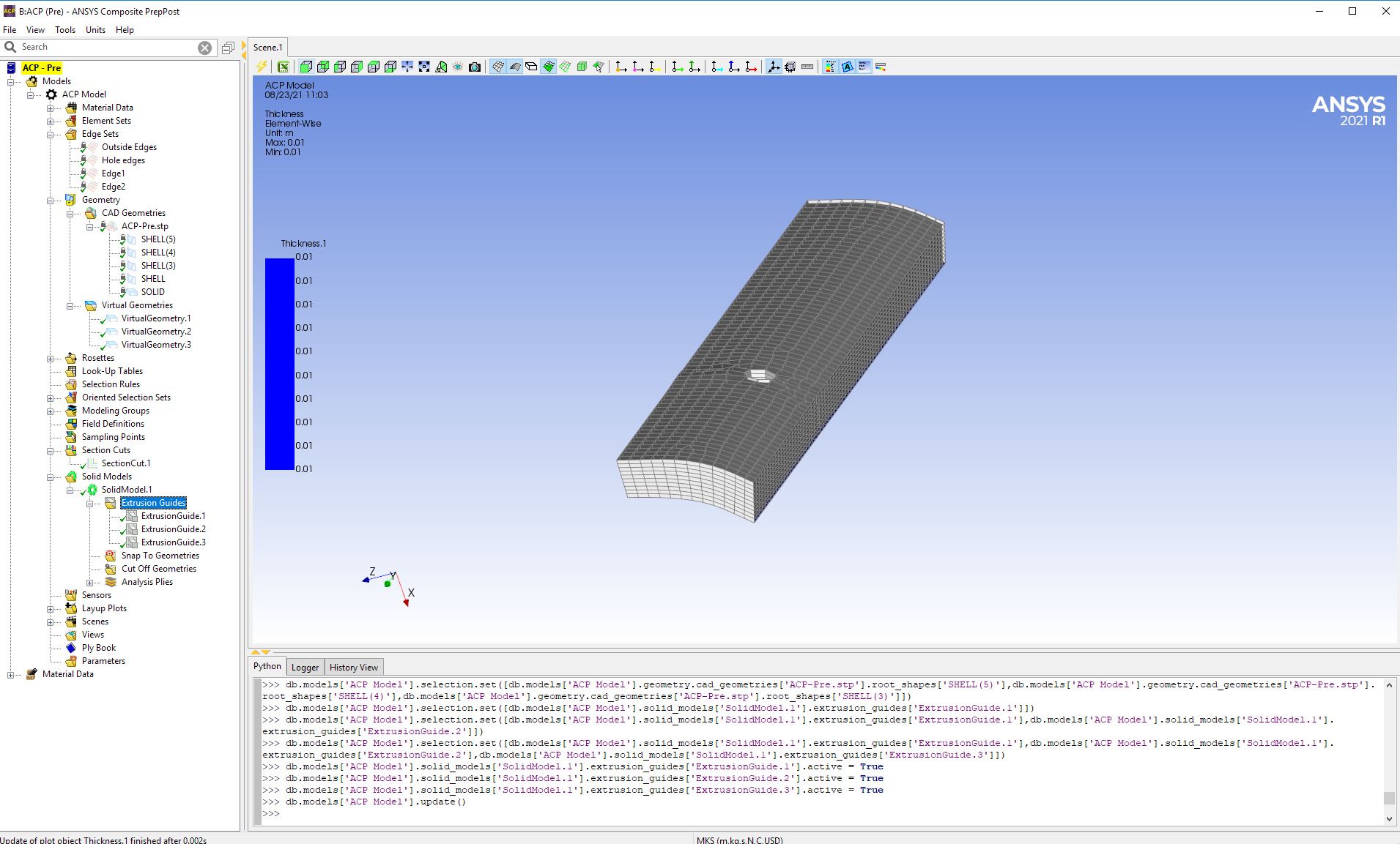
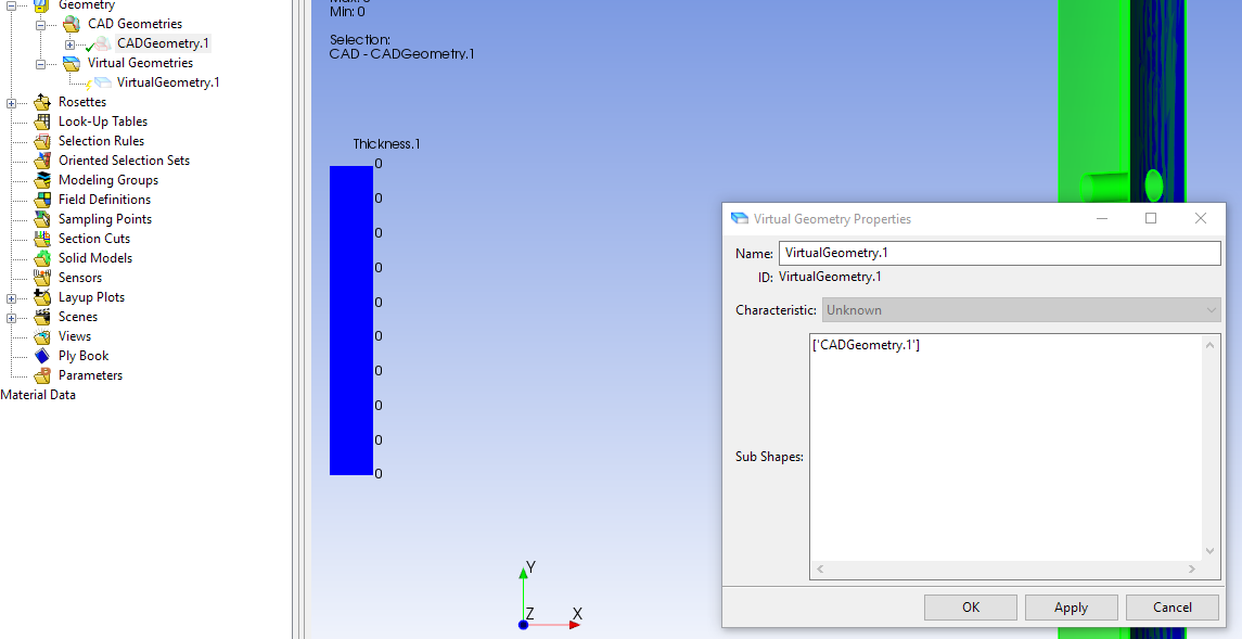
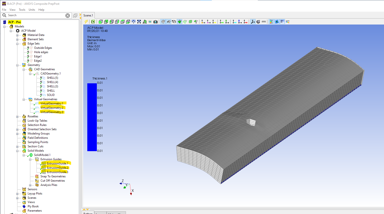
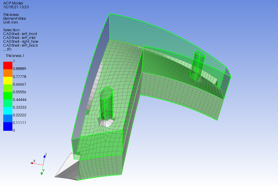
      Here you can see the 3 shell surfaces in ACP

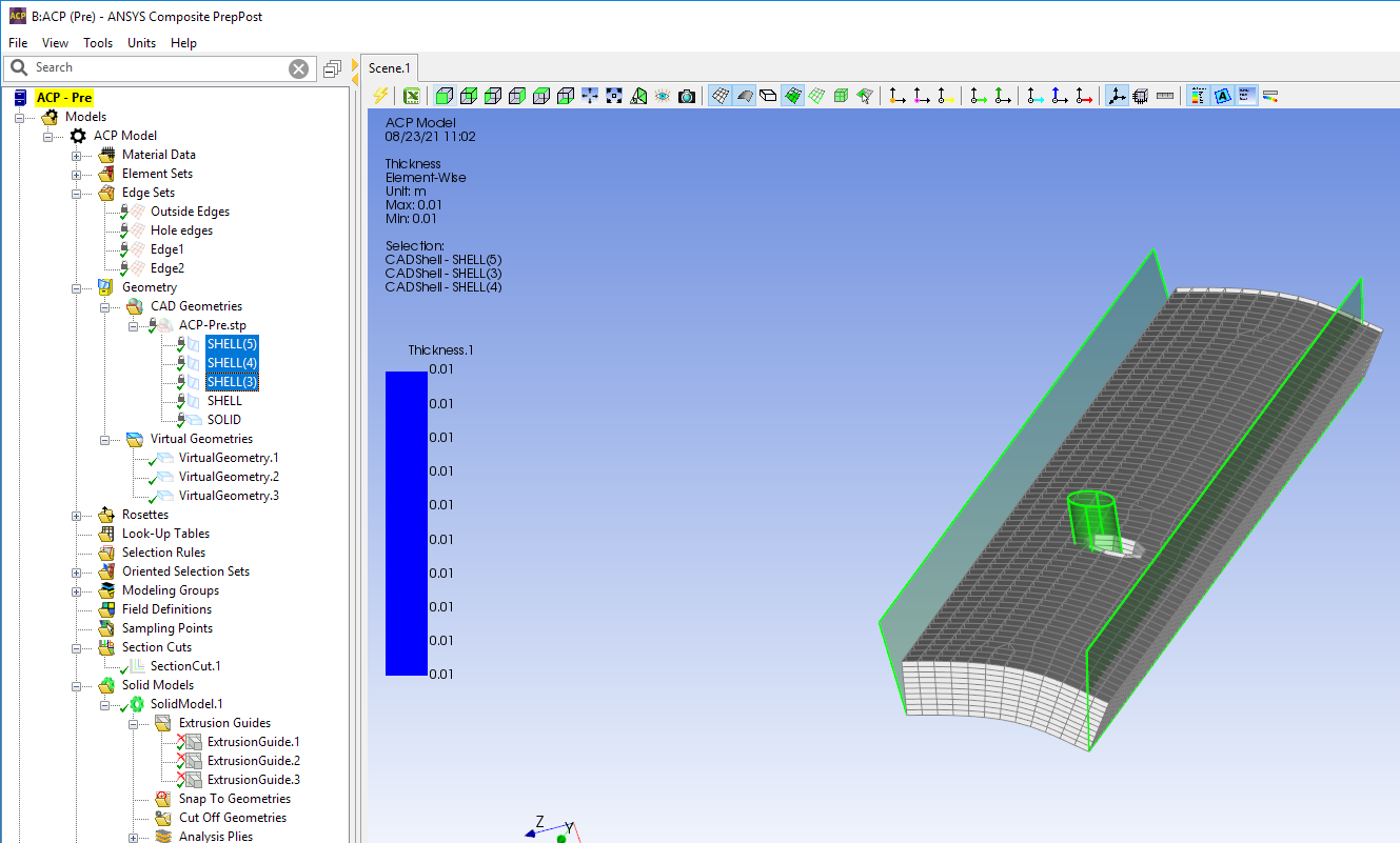
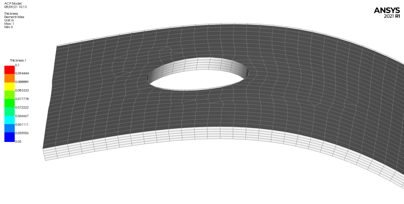
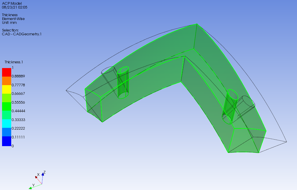
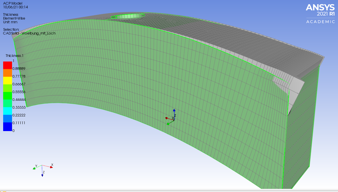
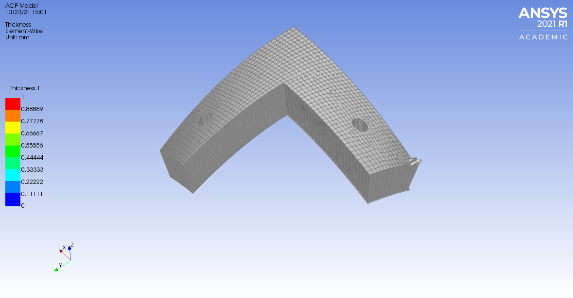
      This is what the normal extrusion looks like w/o using extrusion guides.
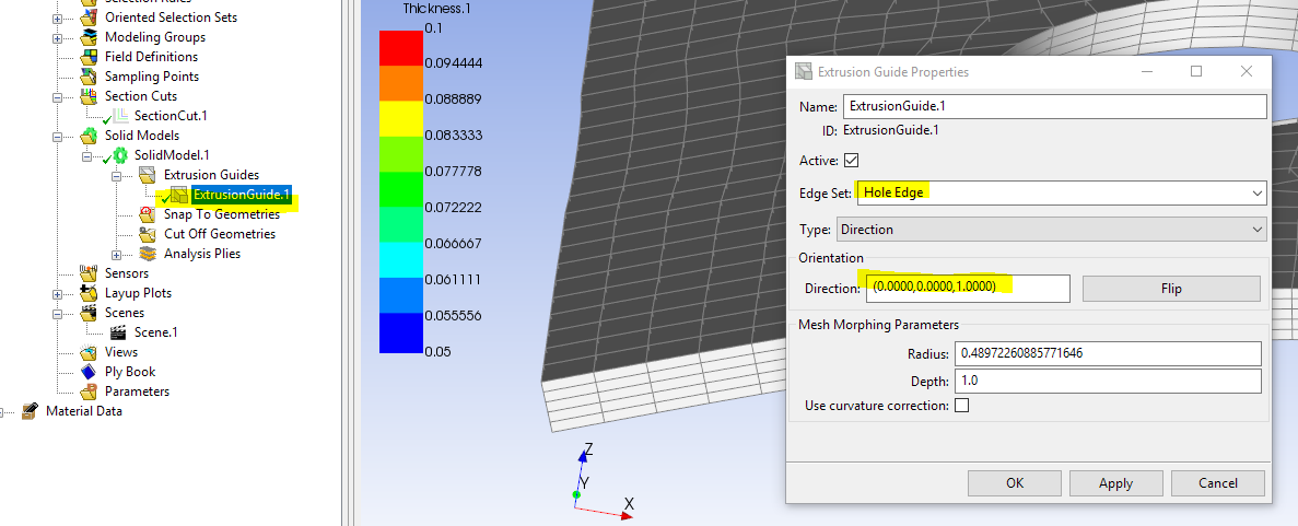
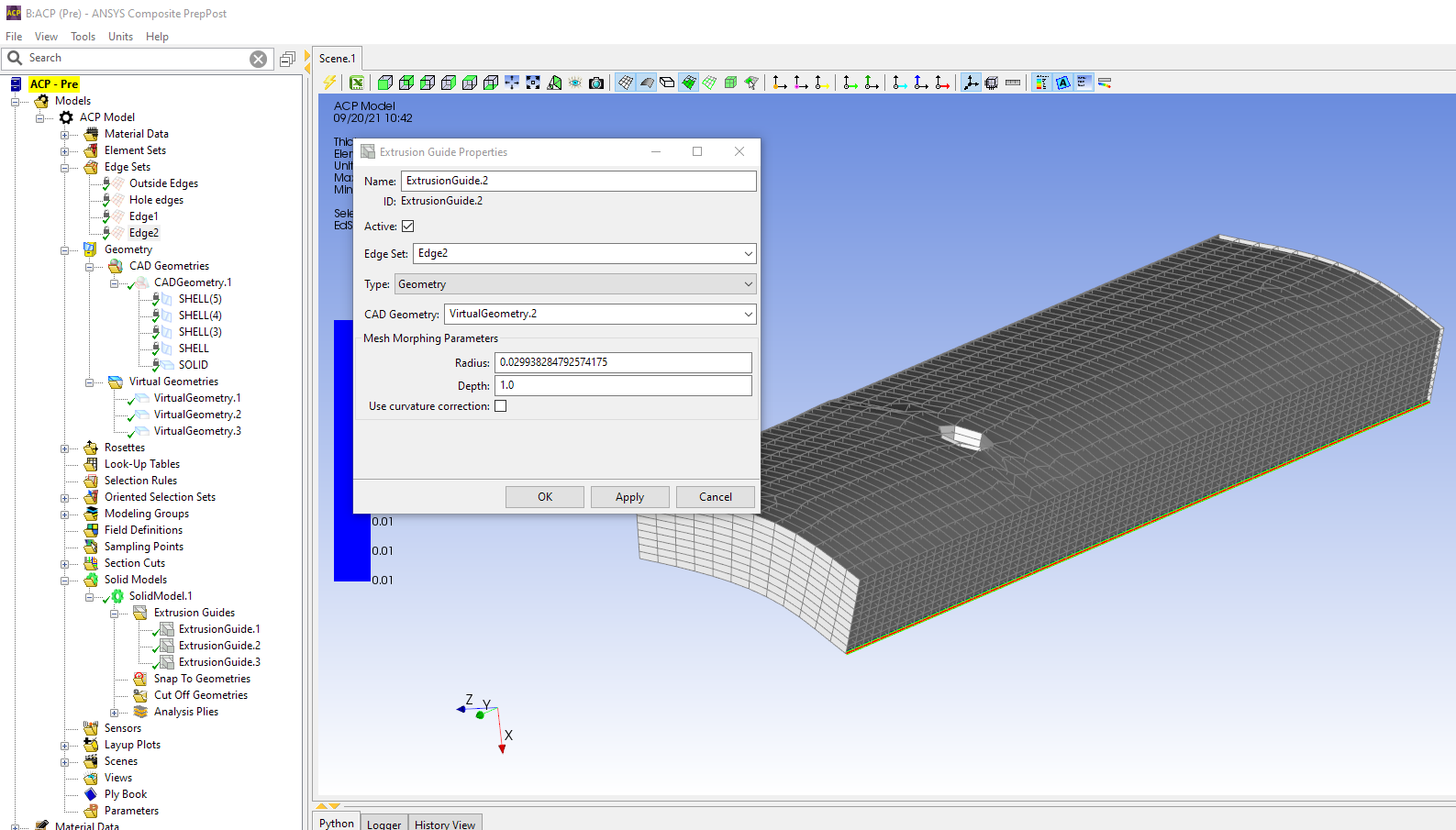
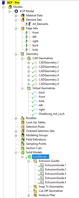
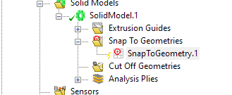
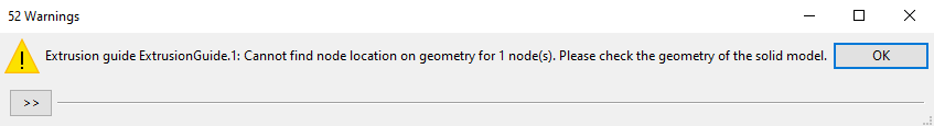
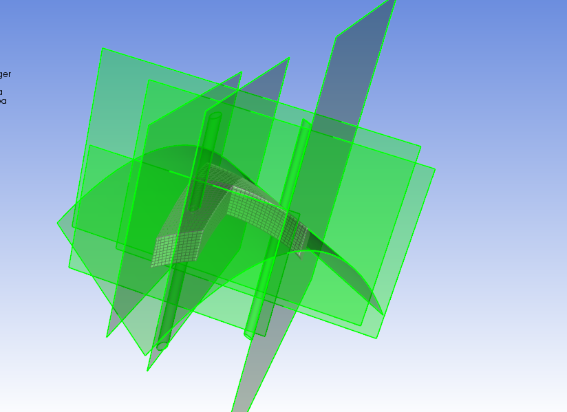
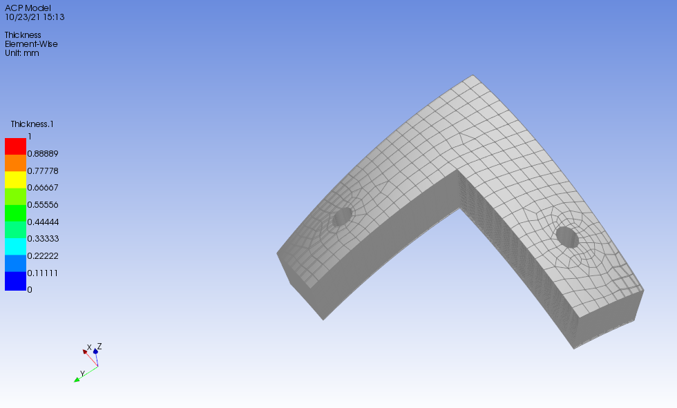
      Now with the 3 extrusion guides (one for each face, and the hole) as individual extrusion guides

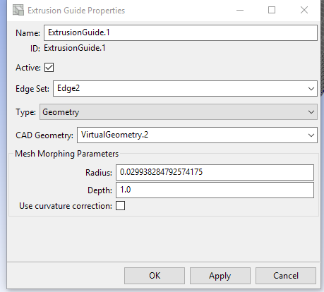
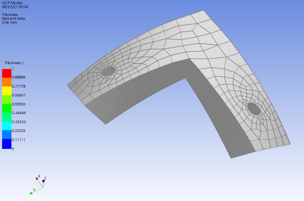
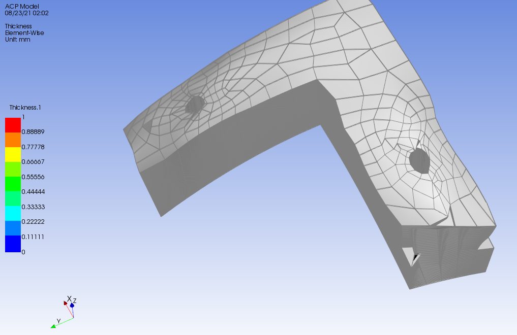
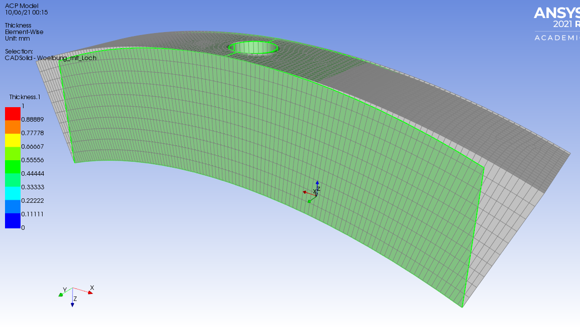
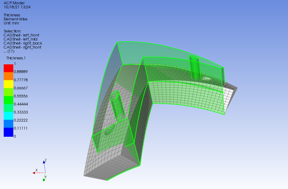
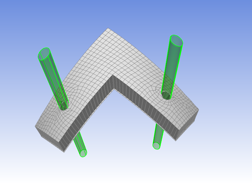
      We get the mesh as shown below. BTW, you can still use type "Direction" in extrusion guide if those surfaces all point in a vector direction, but create an extrusion guide per edge set. When I try with an extrusion guide that has all 4 edges together, my mesh gets deformed.
      Can you try theses methods and circle back with feedback?
      Regards Sean


    • katneckk
      Subscriber
      Hello Sean I have tried but encounter an error message when importing the CAD geometry.
      About my procedure:
      I first imported the geometry and created all side faces in Spaceclaim as shown in the picture.
      Then I created the mesh and first ACP model from the base surface and created the solid model. Then I dragged the connection from A2 to B5 and wanted to import the CAD geometry into ACP (by updating the system) to apply the Extrusion Guide. Unfortunately, this does not work due to an error message. What is wrong with my procedure?

      Best regards


    • Sean Harvey
      Ansys Employee

      That is the same setup I have with the solid and the surfaces. I think I know what is the issue. It seems it happens in the student version and not the commercial version. Are you using the student version? Which version are you using? I confirmed the same error you have with the 2021r1 student version. If you don't have student version 2021r2, please try in that version and let me know. If it still does not work, I will talk with our development to learn more. Thank you!

      Regards Sean
    • katneckk
      Subscriber
      Yes I am using the student version 2021R1. I downloaded the new version 2021 R2 and it still doesn't work. (Picture below)


    • Sean Harvey
      Ansys Employee
      Thanks for confirming. Let me ask our developers and get back to you. Thank you.

      Regards Sean
    • Sean Harvey
      Ansys Employee

      Sorry on the delay, I have checked in again with our development and hope to hear shortly. Thank you.
      Regards Sean
    • katneckk
      Subscriber
      I am glad to hear that! Thank you for asking.
    • Sean Harvey
      Ansys Employee

      After talking with a developer, it appears this is a defect in the student version. I workaround is this. Don't connect the geometry cell to the setup cell. If it is connected already, then right mouse click and delete.
      Next once in ACP-Pre, right click on CAD Geometries and pick Create CAD Geometry.
      Then in the folder box to the left of Refresh, pick that and you can pick the CAD Geometry file. Keep in mind it needs to be .stp or .iges format, so you may need to convert your CAD solid to one of those formats. Just a note: SpaceClaim Academic version does not allow you to save as other formats.

      Once you have the CAD Geometry you create the Virtual Geometry as before.

      Can you try this and let us know if it works for you?
      Cheers Sean

    • katneckk
      Subscriber
      I have also thought about importing the geometry this way. Isn't the method of creating the individual surfaces via copy/paste missing with this option? The import itself works. When I now try true to use the extrusion guide that has all edges together, my mesh gets deformed like it did in the beginning.
      Thanks for the feedback
    • Sean Harvey
      Ansys Employee
      Hello @katneckk Sorry for the potential confusion. Once you import the CAD geometry using this direct import method, you need to create a virtual geometry for each surface. Then in the extrusion guide, you need to pick an edge set and the virtual geometry it pairs up with. Repeat for each edge/surface pair. See the 2nd image. I've done this and was able to get the solid generated as shown. Do not use all the edges together. Please let me know if this helps.
      Regards Sean


    • katneckk
      Subscriber
      Sorry for my late reply. I was away. I have now tried it as you described. Below you can see the screenshots of my project and model. It still comes up with the same error message (as you can see below), as well as the deformed part. I have modeled a curved bar with a hole.
      First the base
      Next the SolidModel without Extrusion Guide
      Next the model with the 5 extrusion guides for the 4 edges and the hole
      Here is a screenshot of my project with the EdgeSets, geometries etc.
      And this is the message/warning i recieve:
      What am doing wrong?
      Best regards


    • Sean Harvey
      Ansys Employee

      Sorry on the delay.
      I believe the issue is during the morphing, the nodes are falling off the surface. Can you extend them so they cover the original mesh? You can see in 2nd image how the green surfaces do not overlay the entire mesh. Also at the top how the nodes you will wish to conform to a specific thickness, you can use the snap to geometry and specify yet another cad surface.
      Please see if this helps.
      Regards Sean

    • katneckk
      Subscriber
      Thank you very much for your reply.
      As far as I understood correctly, I have now increased the dimensions of the outer surfaces and thus applied the Extrusion Guide. I also used the SnaptoGeometry function to achieve the desired thickness. I have now used this method on an L-shaped curved part with 2 holes.
      In some areas of the part this works very well. At others, unfortunately, still not as you can see from the pictures.
      Before Extrusion Guide and Snap to Geometry
      With Extrusion Guide and SnaptoGeometry

      The same warnings with the unknowm node locations appear. (with much less unknown nodes than before)

      Best regards

    • katneckk
      Subscriber
      Small update from my side.
      I have now managed to change the side faces with the ExtrusionGuide seemingly without error. I achieved this by using oversized layers as bounding surfaces. Unfortunately, this method does not work for the holes.(pictures below)
      For the upper part boundary I also used an oversized surface for the snaptogeometry.
      Best regards
    • Sean Harvey
      Ansys Employee

      Glad to see the progress. Let me check with some colleagues and get back with you...
      Thanks Sean
    • Sean Harvey
      Ansys Employee

      I wonder for the holes, if you can pick the edge set, and use a vector and not cad geometry. Can you try that?
      If not, then the other recommendation is to improve the mesh around the holes. You can insert inflation under mesh object in mechanical for the base surface mesh to create elements that are uniformly size and growing in size from the hole outward. This may help when the mesh is being morphed.
      Let me know if this helps.
      Regards Sean
    • katneckk
      Subscriber
      Hi Sean The idea with the vector worked. I specified a hole edge direction of 0,0,1 (Z direction) for the holes instead of an extrusion guide via geometry.
      Do you have an explanation why in this case the setting via geometry does not work?
      Furthermore, it works only with certain element sizes of the mesh. (Pictures are attached) The smaller the element size is given, the worse the SolidModel becomes.
      Do you have an explanation why this is so?
      The approach via inflation did not lead to success.
      Best regards and many thanks for your help!

      3mm element size (no defect/error)
      1.5mm element size (small defect/error)

      1.5mm element size (defect/error getting bigger)


    • Sean Harvey
      Ansys Employee

      Glad there is some progress. I know with morphing, sometimes the mesh size does effect the success. Have you tried changing the Mesh morphing parameters? The defaults I show here are not a reference, just what was in my model when I pasted.
      Not sure if you have access to the help but we explain what these options do there.
      2.1.15. Solid Models (ansys.com)
      If you do not have access to the help, then I can provide a bit of brief explanation. Please let me know. Thanks.
      Regards Sean
    • katneckk
      Subscriber
      Unfortunately, I do not have an account in the Customer Portal and therefore do not have access to your link
    • Sean Harvey
      Ansys Employee

      Ok, since you don't have access to the customer portal, can you please check for the help shortcut in the installation? If you go to the start menu, then Ansys Student version folder, there should be a link to launch help. You will search for

      2.1.15.1.3.1. Mesh Morphing
      In the ACP User's guide.
      Can you confirm?
      Regards Sean
    • katneckk
      Subscriber
      Yes, thank you! There is launch help.

    • Sean Harvey
      Ansys Employee

      Great! You are welcome.
      Regards Sean
Viewing 25 reply threads
  • The topic ‘Orientation of the layer application for curved surfaces in acp (pre)’ is closed to new replies.