-
-
July 18, 2019 at 6:10 pm
shayan23
SubscriberHi eveybody
I'm working on vertebral and disc of an animal
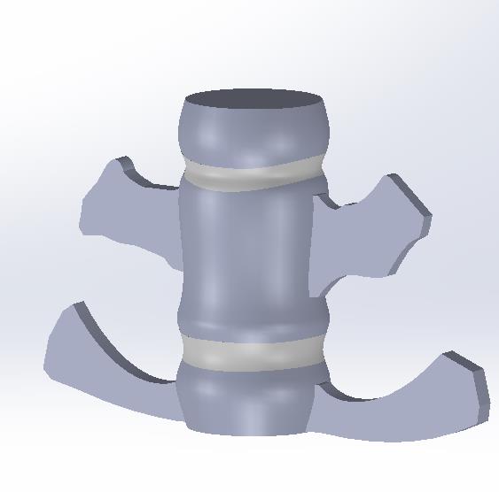
two whites part are disk and others are vertebral Â
I have the Frequency response function(FRF) from experimental test and the goal is to optimize the 3D cad model in ansys to reach the same FRF as test . I approximately optimized the natural frequencies which defines the horizontal position of two first peaks in FRF plot by placing the young's module (E) and poisson's ratio(v) as input parameter and natural frequencies as objective function to achieve the same frequencies as test. for optimizing the vertical position of peaks in FRF plot, i consider the constant damping ratio for each of vertebral and disk in engineering data and set these values as input parameters and set maximum amplitude of FRF as objective function to approaching test FRF and the i obtain these plots :Â
as you see the maximum amplitudes are approximately equal but the overall shape of optimization data near the two first peaks are not same.so how i can solve this problem to obtain closest ansys frf to test frf ? is my considered input parameters for this purpose true ? if not,which parameters should i consider as inputs ?
-
July 19, 2019 at 6:17 am
shayan23
Subscriberanybody can't help me to update ansys frequency response function by test results ?
-
July 19, 2019 at 7:58 am
jj77
SubscriberAssuming you have the exact geometry then, there are really, material properties to play with and damping. Also BC of course.
Â
I would suggest to start increasing damping, first and see what hat gives (that might make the peaks of the FEA FRF broader). Then continue with other properties (say E mod.). And finally when you see the changes individually you can start combining them to get the desired effect.
Â
I have used tools for this in the past when working as consultant in acoustic and vibrations, it is called femtools and does this sort of things (tuning of models to experiments). See if they have a affordable student version which you could use.
-
July 19, 2019 at 11:40 am
shayan23
SubscriberThanks for your respons jj77
if i change the damping then the peaks vertical position goes above the test peaks, and changing E mod will change the horizontal position of the peaks...
could you explian femtools and what it do ? -
July 19, 2019 at 11:46 am
jj77
SubscriberI would suggest to look on their website and contact them directly.
Â
Thank you
Â
PS: I do no think it (femtools) will magically do some wonders - I think what you are doing is very tricky (as material in human anatomy is very complex), and unfortunately I do not have any exp. in that field.
-
August 17, 2019 at 4:32 pm
Mahyarm
SubscriberHi Shayan. sorry... I saw that you wrote that you optimized your frequencies to the test you've done before... could you tell me how can I do this with my beam project just like you?
-
August 17, 2019 at 5:06 pm
Mahyarm
SubscriberHi Shayan. sorry... I saw that you wrote that you optimized your frequencies to the test you've done before... could you tell me how can I do this with my beam project just like you?
-
- The topic ‘optimization of FRF to matching the test results’ is closed to new replies.
-
6485
-
1906
-
1458
-
1308
-
1022
© 2026 Copyright ANSYS, Inc. All rights reserved.

