We have an exciting announcement about badges coming in May 2025. Until then, we will temporarily stop issuing new badges for course completions and certifications. However, all completions will be recorded and fulfilled after May 2025.
Ansys Free Student Software

Ansys Free Student Software

Topics cover installation and configuration of our free student products.

Optical Path Difference

    • Eren Umay
      Subscriber

      Hello,

      I have an optical system in which I want to calculate the optical path difference between two configurations of the system. The system is as follows:

      In the first configuration, there is a point source, a rectangular glass prism of some finite thickness tilted at angle theta with respect to the horizontal, and an objective which is a circular plane. All the light that is captured by the objective has passed through the glass rectangular prism. The second configuration is the same except that there is no rectangular glass prism. Both configurations are immersed in water. Centers of all elements are placed on the same vertical line in both configurations. Attached are the figures of both configurations.

      I want to map the optical path difference and the phase differences (for a given wavelength) caused by this OPD at every point on the objective plane. How can I set up the system, and how can I graph the results in the specified manner?

      Any help is much appreciated.

    • Ethan Keeler
      Ansys Employee

      Hello Eren,

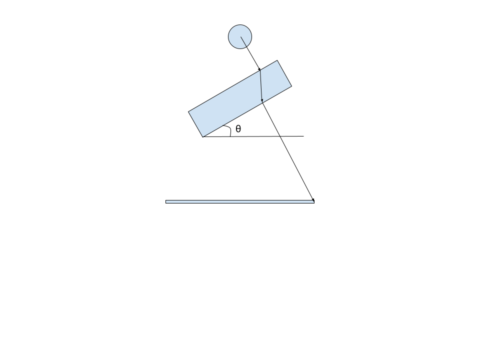
      Thanks for the question! I believe the easiest way to set this problem up would be through OpticStudio Sequential mode. I have built out a simple example for your set-up. I use one Coordinate Break pair to tilt the glass plate, and then another Coordinate Break to tilt the Image plane. It looks a little different from your drawing, but it has the same control over the relative angles of all the planes.

      Then I’ve created two configurations in the Multi-Configuration editor. Using the GLSS operand, I create one case where we assign a typical material (N-BK7) and the other case where it is just air (the ray is not refracted).

      Finally, I can open the Single Ray Trace tool to see the Path Length at each surface as the ray propagates. The Path Length represents the ray path length from the previous surface up to the surface under consideration. You can switch back and forth between configurations to compare the relative Path Lengths. 

      You can then add up all the Path Lengths between the two cases, find the difference, and convert to a difference in phase using the wavelength.

      Let me know if my example in OpticStudio is unclear.

Viewing 1 reply thread
  • The topic ‘Optical Path Difference’ is closed to new replies.