-
-
October 26, 2019 at 7:45 pm
leoansys
SubscriberHi there,
I need to model nonlinear rotational stiffness in a revolute joint to simulate the joint yielding, ie once the joint begins to yield the stiffness of it will decrease, similar to the following:
I am using ANSYS Workbench Mechanical 2019 R2 with a Static Structural analysis. I see the torsional stiffness option is given in units of [Nmm/degree], which would only represent the Ki section of the above graph. My question is, can you use tabular data, or a command to get the nonlinear plot of above?
Note I am new to commands in Workbench, and have tried the following with no success:
Simple beam model with fixed ends, one revolute joint connecting the beams between end vertices, and gravity load:
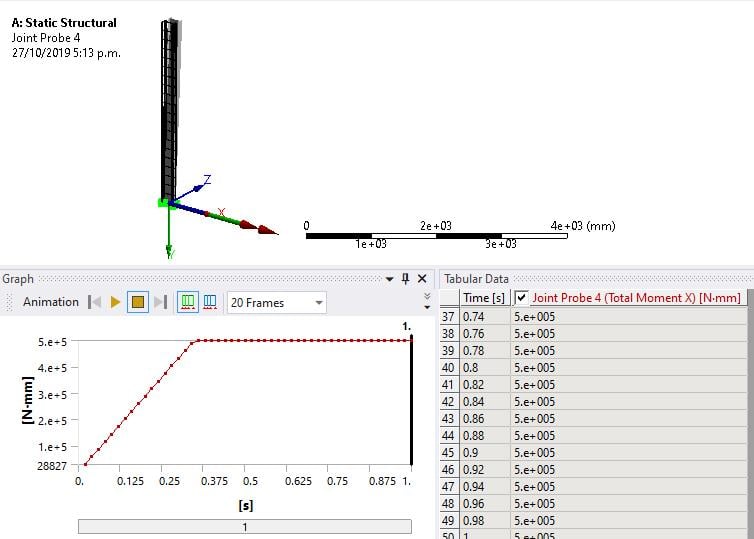
Trying the following command to create tabular data of rotation behavior [degrees] and the corresponding moment [Nmm] with the intention that this is the moment stiffness of the joint will follow when deforming (note the values are arbitrary and not representative of the bi-linear graph).Â
This command appears to apply a moment to the joint, whereas I want the joint to change stiffness as the joint deforms:
Any help would be much appreciated, and it would be good to know if you can extend this to more degrees of rotational freedom, ie also about the y-axis.
-
October 26, 2019 at 8:45 pm
peteroznewman
SubscriberHi Leo,
Look into a COMBIN39 spring element. That can give you the exact bilinear function you illustrate above.
/forum/forums/topic/how-to-access-the-ansys-online-help/
This element can represent torsional springs using KEYOP,3,6 to define the degree of freedom to be rotation around the Z axis.
In Mechancial, insert a spring element under the Connections folder, then add a Command Object to change the element to COMBIN39 and provide the Real Constants.
-
October 27, 2019 at 4:17 pm
leoansys
SubscriberThanks Peter.
I got the rotational spring to work using your suggestions. I also had success using the TB,JOIN function too. My model consisted on a simple cantilever beam with a Universal Joint near the fixed end. I specified the following command on the joint for bi-linear stiffness in 2 rotational DOF (both negative and positive):
I then displaced the beam at the end in both directions to see the behavior, and as expected, the moment in the beam plateaus at the yield moment as specified:
I found this method more useful for post-processing, as you can obtain joint angles, forces, and moments for validation purposes.
Thanks again for your help,
-
October 27, 2019 at 4:37 pm
peteroznewman
SubscriberThat's great Leo!
You should mark your last post with Is Solution to show your preferred solution. This also marks the discussion as Solved so members can see that without having to open the discussion.
-
October 13, 2020 at 2:13 am
mateusredin
SubscriberHi guys!nI was reading the topic and realized that there is an easier way to solve this problem.nIf you check the documentation, you'll see that you can add nonlinear moment-angle relations with tabular data only for bushing, general Joints, and Radial Gaps. So you could substitute your revolute joint for a general joint with equivalent DOF unlocked.nOnce you selected your general joint in the tree, click Worksheet, and then you'll be able to right-click the corresponding stiffness cell and select Tabular data.nDespite the topic being already solved, thought it might be useful to someone.
-
- The topic ‘Nonlinear Revolute Joint Rotational Stiffness’ is closed to new replies.
-
6019
-
1906
-
1425
-
1308
-
1021
© 2026 Copyright ANSYS, Inc. All rights reserved.


