TAGGED: contact
-
-
May 10, 2024 at 11:48 am
shasa.nicoloso
SubscriberHello everyone,
I'm experiencing some issues with a simulation of the bending of a surgical staple.
I verified the plasticity of the material used first with a simple transient analysis with large deformations of a beam and all worked fine. Right now I'm performing the contact analysis with a simplified model of the leg of the staple to ensure the right contacts for the last simulation.
The setup is the following: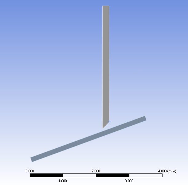
The leg is set to flexible and the plane is set to rigid.
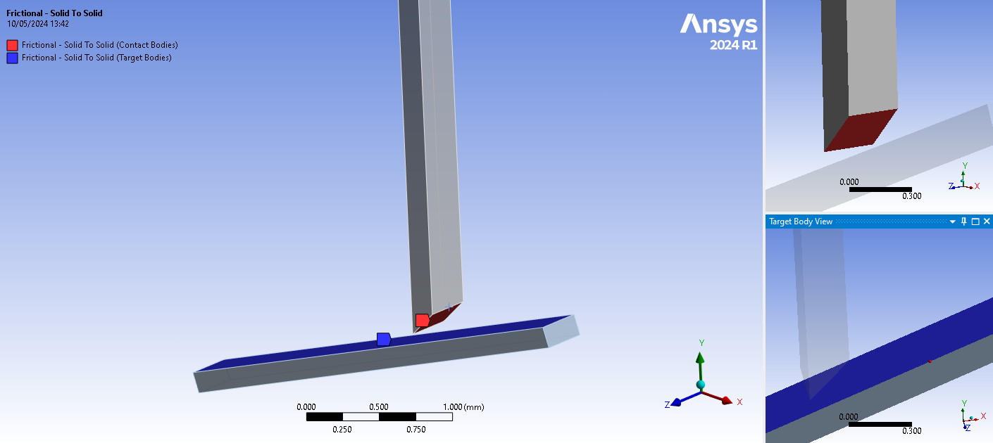
Contacts are set to frictionless, i tried many configs but none of them worked. First of all with penetration issues where the leg compenetrate the rigid body like is not detecting the base. secondly I continuosly get the warning
"One or more MPC contact regions or remote boundary conditions may have conflicts"
If some of you may have encountered the same situation or has any suggestion it would be appreciated.
Right now I'm wokring in Transient structural with the following setup:
Thank you all in advance
-
May 11, 2024 at 12:21 pm
peteroznewman
SubscriberHello Shasa,
I like that you are creating simple models to incrementally get new pieces working, rather that trying to get a complicated model working all at once.
I see that you have inserted a Contact Tool under the Connections folder, which is always recommended for any nonlinear contact use. Please Generate the Initial Contact Status and show the table. Is the contact Near Open or Far Open? If it is Far Open, edit the Contact and change the Pinball Region so you can type in a Pinball Radius that is larger than the gap between the two surfaces.
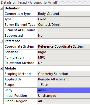
The MPC warning might also be an issue. I see you have a Fixed Joint and I assume that is to hold the rigid body in place. Which side of the tilted block was selected? If it was the same side as the contact, change the Fixed Joint to use the side opposite to the contact surface.
While you can get the Transient Structural model to run, it will take less a bit less time to solve if you change the analysis type to Static Structural. You can do that in Workbench by right clicking on the top of the block. The bending of a staple does not generate high inertia forces because the accelerations are low which is why Transient is unnecessary. If you change to Static Structural, you may have to manually turn on Large Deformation under the Analysis Settings because the default is off under Static Structural, but the default is on under Transient Structural.
Finally, under Analysis Settings, make sure to turn on Auto Time Stepping and use a lot of substeps to gradually bend the staple leg. In Transient, the substeps are defined using time, so you define a small value for the Maximum Substep time, and that value is small relative to the End Time for the step. In Static Structural, the End Time defaults to 1 s and the substeps are by number so you define a large number for the Minimum Substeps to use a lot of substeps to gradually bend the staple leg.
Try these and see if you get what you want. If it is still not working, there are some other things to try.
Regards,
Peter-
May 17, 2024 at 2:55 pm
shasa.nicoloso
SubscriberThank you for the reply,
Actually I followed the suggestions, moved to static structural for the simulation of the simmetry model (beacuse it is supposed to be).
I show the actual running setup in the detail, beacuse problem moved to non convergence of the simulation:
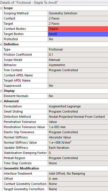
Contacts
This time the contact works without the pinball radius definedJoint
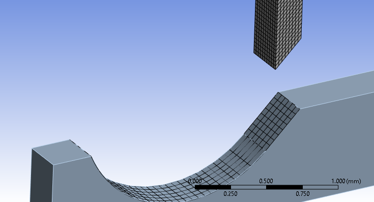
Mesh
Is set to mechanical, should move to nonlinear mechanical?
For the staple I used a sweep method for meshing and body sizing at 0.03mm
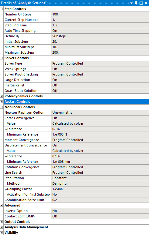
For the Anvill I used a face sizing at 0.05mmAnalysis Setting
I’m trying many different config for the many controls, so if there is something which is wrong or bad for the simulation pls let me know.
Boundary conditions
 Frictionless is applied in the middle of the staple to reproduce the symmetry.
Convergence
The model is actually running, due to the weight of the model is not so fast (work’s pc not a big perfomer).
If you have any sign of bad convergence that i do not see just let me know.In the end…
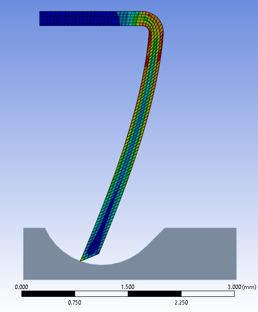
With the static structural i got till here, the last simulation before the before shown setup stopped here:
Due to convergence problems i got many bisections in the process, I’ll figure it out how to avoid em with step reduction.
Thank you in advance for allRegards,
Shasa
-
-
May 17, 2024 at 6:47 pm
peteroznewman
SubscriberIt seems you selected to the top face of the staple to apply the Displacement BC. A better method of squeezing the staple against the fixed anvil would be to introduce another rigid body that would press on the top face of the staple. That second rigid body would have a Translational Joint to ground and a Joint Load of type Displacement to squeeze the staple. That would allow the staple to lift off the rigid body as the arm is bending. The displacement BC prevents the top face from moving out of plane which is not realistic.
-
- The topic ‘Nonlinear plastic simulation contact issues’ is closed to new replies.


-
3487
-
1057
-
1051
-
955
-
922

© 2025 Copyright ANSYS, Inc. All rights reserved.

