TAGGED: non-linear
-
-
March 15, 2024 at 1:26 pm
Raphaël BEVAN
SubscriberGood morning everyone,
We are French engineering students working on a project for our school. The project is to study the impact of a car on a fence. First of all we have designed on SolidWorks the fence and a cube to simulate the car (SolidWorks files are attached in the post).
It’s look like this :
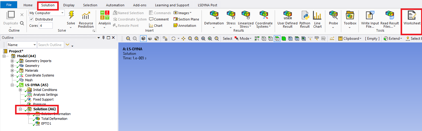
So in Ansys Workbench, we take the function “ Static structural “
And we import our Geometry in “.step”.
In the Engineering Date we delete Structural Steel and choose on the bookshelf “ General Non linear Material “ we have taken Structural Steel NL for the fence and Structural Steel S235J for the cube and fixation parts.
For our settings we chose :
Contact :
Every contact is automatically generated by ANSYS (bounded) but the contact between the cube and the fence we choose is frictional with a Friction Coefficient of 0.2 because there is a slipping between the cube and the wire of the fence.
We try to put the cube “rigid” but when he passes on this statement we can’t apply the force on the cube like explained below.
Mesh :
We’ve tried to decrease the element size to 100 mm without success.
Analyze Settings :
Large deformations are activated which is very important in our case. We’ve tried using more increments without success.
Force : We need to apply 50 000 N on the cube along the Y axe.
We’ve found some advice on the internet and it’s said to apply step by step the effort. We’ve never had results above 20 000 N.
We also add the standard Earth Gravity.
Displacement : Displacements of the cube are set to 0 mm on both X and Z axes to avoid the sliding of the cube. Y axe is set to free. The goal is to create a sliding connection.
Fixed Support : In real life the fence is fixed using a bolt and recreated with fixed supports in ANSYS.
In conclusion, we need help to solve this problem with a force of 50 000 N. We can also send you the Ansys file if needed. Thank you in advance for your help and your time.
Best regards,
-
March 15, 2024 at 5:21 pm
Armin
Ansys EmployeeHi Raphael,
As a suggestion, this type of simulation (impact test) is much easier using an explicit solver. The Static Structural analysis system uses the implicit time integration method. You can employ Explicit Dynamics (AUTODYN) or even better than that, the Ansys LS-DYNA solver available in Ansys workbench that are robust for short-duration events with significant nonlinearities. Then try applying the impactor load as a velocity-based boundary condition (rather than force-based) under Initial Condition. If this is of interest, check out the course below to learn more about explicit dynamics analysis:
Explicit Dynamics Theory - Ansys Innovation Course - YouTube -
March 26, 2024 at 9:56 am
Raphaël BEVAN
SubscriberHi Armin,
First of all, thanks a lot for your quick answer.
Last week we tried to apply your advice.
First of all, we don’t have LS-DYNA so we tried with Ansys Explicit Dynamics. We have also took a look at the youtube playlist you have shared, but it's very theorics so we don't understand wich setting we need to adapte.
But we still have some difficulties because the time of the calculation is estimated at 400h by ANSYS so it’s not normal I guess.
We have applied your advice to not use strength and use velocity. That’s why in Initial condition we put 2780 mm/s and applied this velocity to the cube.
I will explain our model. If you have some advice to improve it or if we make mistakes, your help would be greatly appreciated.
First, it’s the same model, we just have changed the mass of the cube to have the reel inertia.
For the mesh :
Initial conditions : Velocity
Analyse settings :
Same fixed supports and same displacement.
We think we don't have all the keys to understand all the settings and which ones impact our model and the time of the calculation.
Thank you in advance for all the answers you can give us.
Best regards
-
March 26, 2024 at 2:11 pm
Armin
Ansys EmployeeHi Raphael,
Try bringing the car (impactor) into close proximity of the fence so the two objects are "just touching" before the impact. This saves some simulation time and doesn't affect the accuracy of simulation since you have already defined a proper initial velocity at impact.
Try using a smaller "End Time" under Analysis Settings, something like 0.002 seconds and increase this value after checking the initial run if necessary.
If your mesh is too small, it will increase the simulation time. Remember that the time step size is dictated by the smallest element of the model in explicit dynamics analysis.
After trying the suggestions above, if your run time was still not reasonable, look up online for a technique called "mass scaling". The theoretical aspect of this technique is covered in Lesson 2 of the course I shared with you earlier: Time Step in Explicit Dynamics - Lesson 2 (youtube.com)
-
March 29, 2024 at 7:56 am
Raphaël BEVAN
SubscriberHi Armin,
Thank you again for your prompt feedback, I have applied your advice and we are still with a calculation around 48h.
We know it’s not a simple geometry but I think Ansys is able to work with more complicated models and I think we forgot something to complete our calculation.
Our fence is like that :
And we want to compare our model with real life tests we have realized. To explain quickly, we pulled on a beam (symbolized here by the cube) and measured the deformation as a function of the force applied. We want to validate a model who is giving close results to our tests.And during our real test, it took us around 10s to remove the ties but if we make a model of 10s we have a time of resolution of 400h.
Do you think it’s possible to do it with Dynamics Explicit ? and how ? Is LS-DYNA a better solver for those long calculations (end time > 1s) but with highly nonlinear deformations ?
Thank you for your help.
Best regards
-
April 1, 2024 at 3:03 pm
Armin
Ansys EmployeeHi Raphael,
Thanks for the update. Here are a few suggestions to reduce the computational time of your model:
- Try to find the smallest element that is controlling the time step size in your analysis. See if you can increase the size of this element. In general, the use of uniform element size is recommended for explicit dynamics analysis.
- Use multiple cores to run your analysis. This can be controlled under the Solution tab in the workbench.
- Look up online numerical techniques of "mass scaling" and "time scaling". They can help to significantly reduce the run time of your model but be cautious that when using these, you must check a few outputs, particularly energy plots, to make sure the results are reliable. The parameters associated with these can be found under the Analysis Settings.
For impact type problems, I found Ansys LS-DYNA more robust, but you can try the steps above first to see if you get any improvements.
-
April 9, 2024 at 9:01 am
Raphaël BEVAN
SubscriberHi Armin
We finally have access to LS-DYNA and thanks for this advice, the calculation time is much quicker.
So now without any optimization we have 40h, I will show you our model, if you have any advice to reduce the time again it will be incredible for our work.
So it’s the same model as before.
For the mesh we have choose this settings :
We have put this analysis settings :
We have the same displacement and fixed support.And we put 0 N at 0s and 50000 N at 0,2s for the force
Do you see any upgrade possible in our model?
Do you know if it's possible to know the maximum deformation of each element of a wire at the end of a calculation? The goal is to find out if one of the wires in our barrier has stretched locally by more than x %.
Otherwise thank you for all your answers during the month.
Best regards,
-
April 9, 2024 at 5:25 pm
Armin
Ansys EmployeeHi Raphael,
I'm glad to hear that you made more progress in your model using Workbench LS-DYNA.
In the 2nd picture you sent, see the entry "Automatic Mass Scaling" that is set to No. This is where you can work on the speed of your simulation by utilizing mass scaling. However, as mentioned earlier, this option should be employed with caution and if you have already obtained reasonable results without using mass scaling, I would suggest you proceed with it.
As another suggestion, you can give the object an initial velocity instead of force since in impact tests you likely don't have the force information at hand, and you only know the velocity at impact.
You can find the maximum principal strain in the wire. Before running the analysis, select Analysis Settings, and then set "Strain" under Output Controls to Yes. After running the analysis, select the Solution branch, and then click on the Worksheet (picture below) where you can report EPTO1 which is the major principal component of the total strain.
-
-
May 13, 2024 at 12:27 pm
Raphaël BEVAN
SubscriberHi Armin,
Thanks a lot for your help from the beginning and for your latest advice, it saves a lot of time.
If I contact you one more time, it’s to ask another question about LS-DYNA.
We wish to have the effort in our fixed support. We want the effort in every axes (X,Y,Z)
We tried some things with “Force Reaction” in “solution information” but the values were not logical so we think it’s not a good method.
We looked on the internet but we didn’t find anything interesting. that is why I contact you to know if you have any idea how to obtain those values ?
Otherwise thank you for all your answers during the month.
Best regards,
-
May 13, 2024 at 3:46 pm
Armin
Ansys EmployeeHi Raphael,
No problem. To check the reaction forces, you can drag-and-drop the desired fixed support onto the Solution Information branch (check the screenshot below) but I suspect that this will produce the same Force Reaction you might have seen earlier if the support was selected properly.
To verify your explicit dynamics simulation, it is always a good practice to check the energy summary. You may find this forum thread helpful:
Successful explicit analysis (ansys.com)
-
- The topic ‘Non-linear calculation that fails, Deformation of a fence following an impact’ is closed to new replies.
-
2457
-
931
-
599
-
591
-
586
© 2025 Copyright ANSYS, Inc. All rights reserved.