-
-
September 27, 2024 at 8:53 pm
zoelle.wong
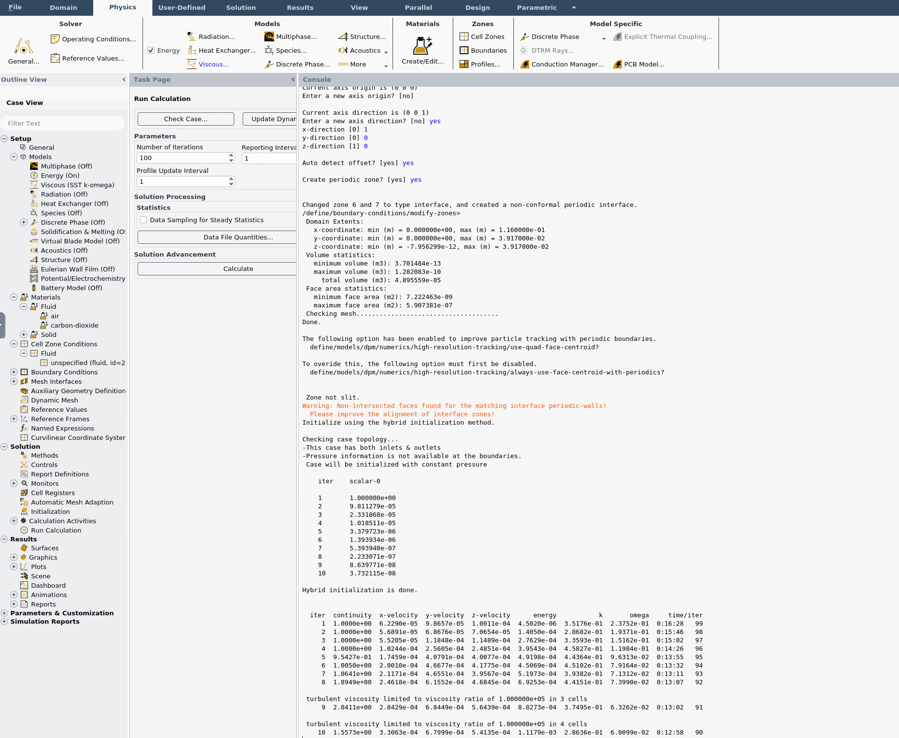
SubscriberI have experience with creating a periodic boundary conidtions, but I've never seen this issue before: Non-Intersected faces found for matching interface periodic-walls! Please improve the alignment of interface zones!
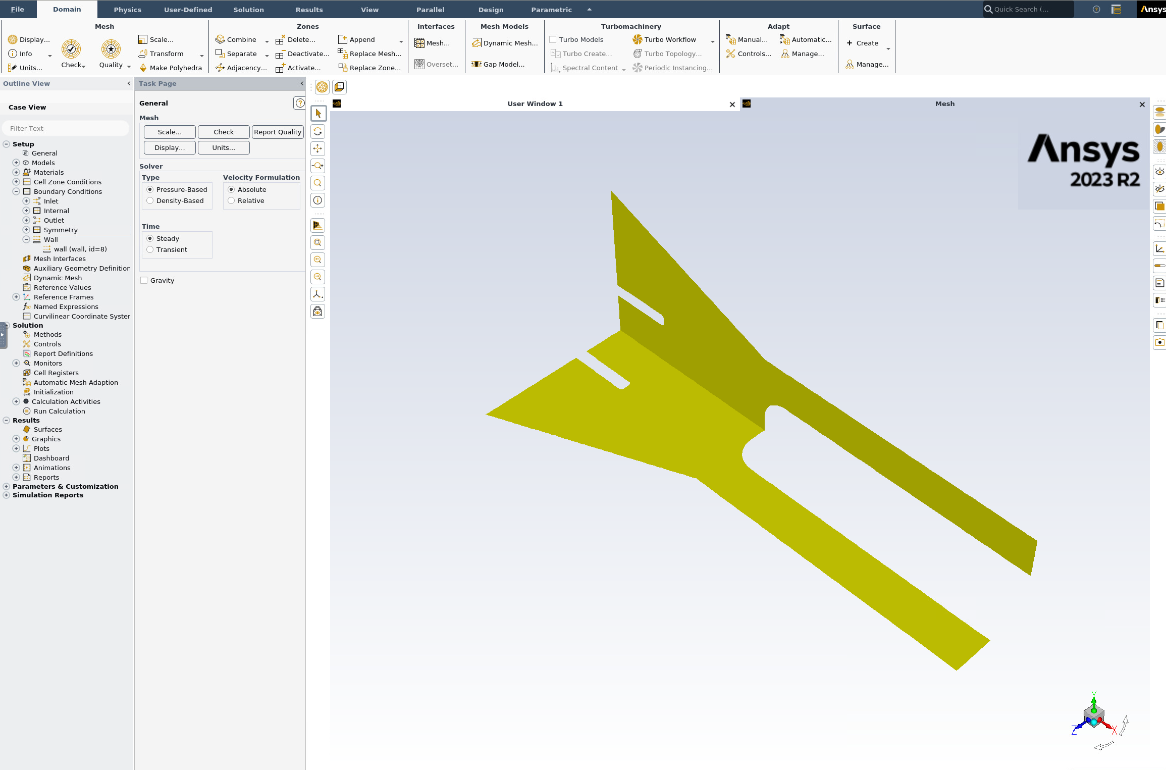
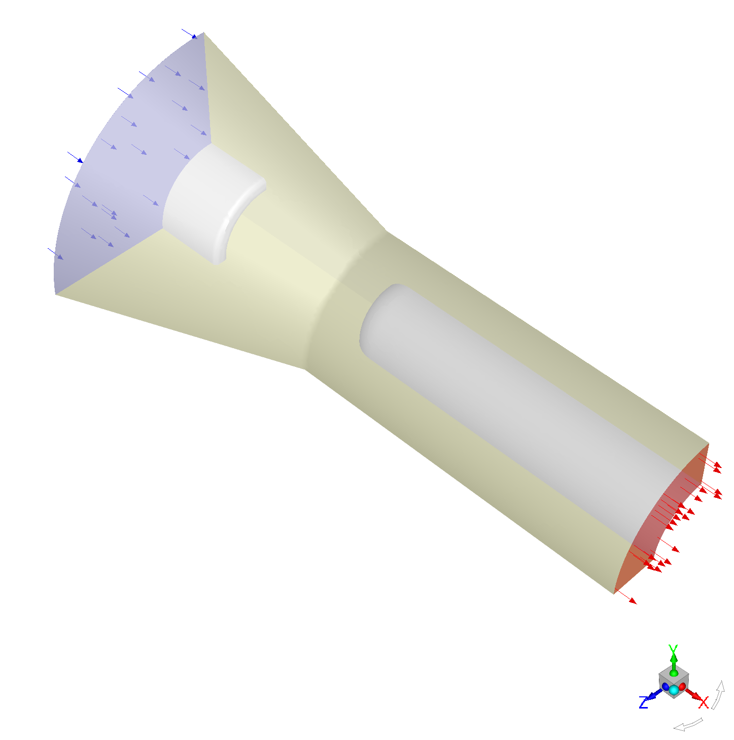
The off-set was automatically set; how can I check the off-set for my current setup? The walls that I'm specifying as periodic are in the second screenshot below. Thank you!
-
October 1, 2024 at 12:18 pm
Rob
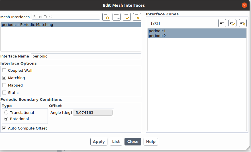
Forum ModeratorCheck what's set in Mesh Interfaces and also under Periodic in the Boundary Conditions menu.
-
October 7, 2024 at 3:46 pm
zoelle.wong
SubscriberI used the "auto" off set and ANSYS automatically computed -5deg. What can I do in the mesh to improve the offset?
-
October 7, 2024 at 4:05 pm
Rob
Forum Moderator5 degrees? Can you confirm as the image looks a little larger than that.
-
October 7, 2024 at 7:32 pm
-
October 8, 2024 at 8:46 am
Rob
Forum ModeratorThat's right, but the angle looks closer to 90 degrees.
-
October 8, 2024 at 2:49 pm
zoelle.wong
Subscriberah i see- the angle between the two faces are 90deg. should i change the mesh such that the angle between the two faces is 180deg?
-
October 8, 2024 at 2:59 pm
Rob
Forum ModeratorNo, 90 degrees is generally a good angle - you've reduced the cell count but not created a sharp angle at the axis. It's the right choice in many cases.... The solver is usually very good at the calculation. Can you set the fluid rotation reference (axis) to x (default is z) and recalculate? I'm wondering if that's an issue.
-
October 8, 2024 at 3:07 pm
zoelle.wong
SubscriberFor the solver, i set it to be an auto conformal, origin at (0,0,0), axis of rotation (1,0,0,), and the auto-offset was calculated as -5deg. I think the offset might be too large; I did manuall decrease the offset at different angles less than 5deg but then the periodic BC wasn't built
-
October 8, 2024 at 3:15 pm
Rob
Forum ModeratorThe offset should be equal to the angle between the two periodic boundaries.
-
October 8, 2024 at 4:29 pm
zoelle.wong
Subscriberthank you that worked! changing the offset to 90deg fixed the issue. lastly- how can i check the periodic BCs are being enforced correctly? there's a way for me to "mirror" the blocks but would that be showing the mirrored BCs or projecting the flow field results as a mirror image?
-
October 9, 2024 at 8:48 am
Rob
Forum ModeratorDon't mirror, use Periodic Instancing from the ribbon. Display tab. It's changed since I last looked at the function too.
-
November 19, 2024 at 3:21 pm
zoelle.wong
SubscriberHey ANSYS team,
I have a follow up question related to this problem set up. I ran my periodic BC case and compared the results to a 2D Axisymmetric and fully revolved case. The inlet/outlet/wall boundary conditions are the same for all 3 cases. My 2D Axisymmetric and fully revolved case approximately match in terms of flow field comparisons, but the periodic BC does not.
I varied equation of state, checked the peridodic conditions for my periodic boundary condition, but the periodic BC results did not change. My shadow/periodic faces match to be conformal
I build my conformal, periodic BC with these inputs: origin [0,0,0], axis [1,0,0], auto offset
Sometimes the auto offset is computed as +/-90 deg
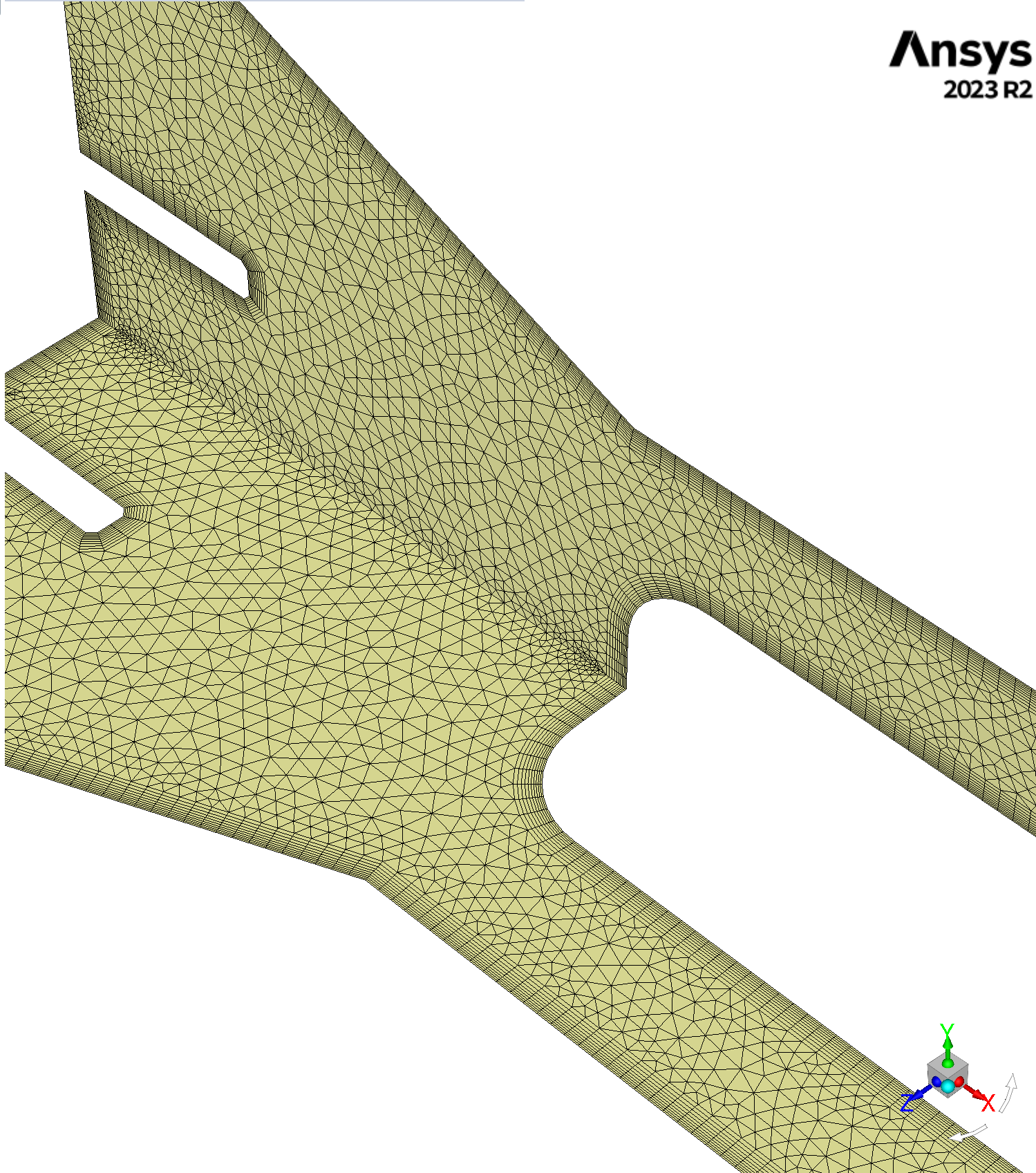
Is there something that I'm missing? I haven't had this issue before so I wasn't sure if its due to the internal structures inside my domain (see below). Thank you again so much for your patience!
-
November 19, 2024 at 3:32 pm
Rob
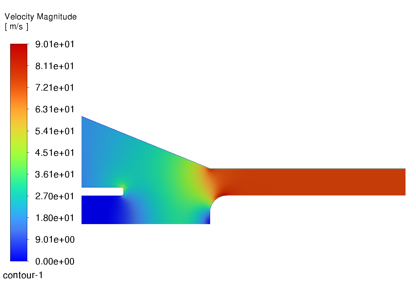
Forum ModeratorWhat's the inlet boundary condition? Images may help - otherwise I can't see anything wrong given what you've said.
-
November 19, 2024 at 3:38 pm
-
November 19, 2024 at 3:40 pm
Rob
Forum ModeratorYes, so you used a mass flow that's the same number in each case. What is the inlet area in each case? Use the surface integrals to find the value in Fluent.
-
November 19, 2024 at 3:44 pm
zoelle.wong
Subscriberperiodic case inlet area: 0.0010661001 m^2
fully revolved case inlet area: 0.0042639739 m^2
the fully revolved case inlet area matches my hand calculations
-
November 19, 2024 at 3:45 pm
zoelle.wong
SubscriberI checked the outlet surface areas; the periodic BC case doesn't match my hand and fully revolved case
-
November 19, 2024 at 3:48 pm
Rob
Forum ModeratorNow divide the fully resolved area by the periodic area. Also read how Fluent handles 2d-axi volumes.
What would happen if you put the same mass flow into each case? Think carefully!
-
November 19, 2024 at 4:02 pm
zoelle.wong
SubscriberAhh I see. I thought the solver would have internally scaled the mass flow inlet BC to the fully revolved case in the back end. I didn't have to scale the inlet BC for the 2D axisymmetric case!
Thank you so much this was helpful- I am now getting results that I am expecting!
%%%%%%%%%%%%%%%%%%%%%%%%%%%%%%%%%%%%%%%%%%%%%%%%%%%%%%%%%%%%%%%%%%%%%%%%%%%%%%%
For future readers who were stuck like me: I divided my mass flow inlet BC value by 4 because the inlet area was 1/4 of the fully revolved area. So for periodic BCs, you need to scale your mass flow inlet value relative to the inlet face area that you start with.
-
November 19, 2024 at 4:13 pm
Rob
Forum Moderator2d-axi is equivalent to 2PI radians so won't need scaling https://ansyshelp.ansys.com/account/Secured?returnurl=/Views/Secured/corp/v242/en/flu_ug/flu_ug_sec_report_conventions.html
Modelling a 1/4 of the domain may well do! Periodic is to help the solver work out how to handle what leaves one rotational boundary and what arrives at the other side.
-
November 19, 2024 at 10:25 pm
zoelle.wong
SubscriberFollow up question- I wasn't sure if it was better to make a new discussion post; but I am more than happy to do so.
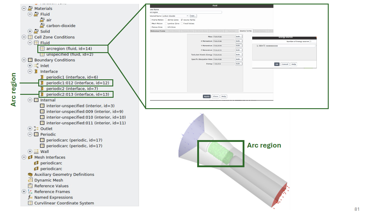
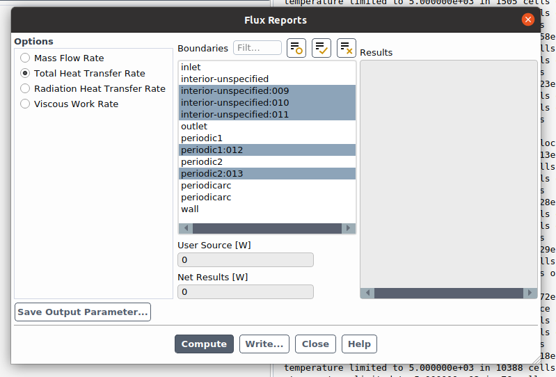
I'm specifying an internal boundary condition inside my domain. My method is to partition the domain such that a cylinder exists inside the volumetric domain. Consequently, I have 2 sets of interfaces: one for the cylinder and one for the domain outside the cylinder. Within the cylinder, I specify an user-defined-scalar such that my user source value in [W] meets a specific value. I check this value by going to Flux report >> Total heat transfer rate >> select boundaries_in_cylinder_region.
- Since the output is in [W], can I assume that the user specified value from the flux report is solely for the quarter cylinder? In other words, is this value independent of periodicocity?
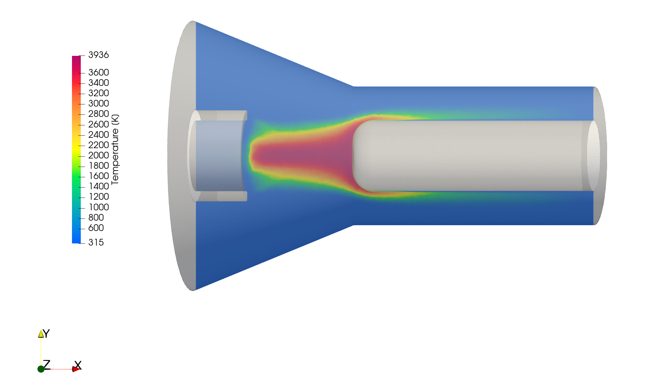
- When comparing the fully revolved case with the periodic BC case, the temperature flow fields look different. I checked my boundary conditions and I'm confident I specificed the periodic BCs correctly. I'm struggling with identifying what is causing the difference in temperature profiles. Do you think this is an outcome of symmetry?
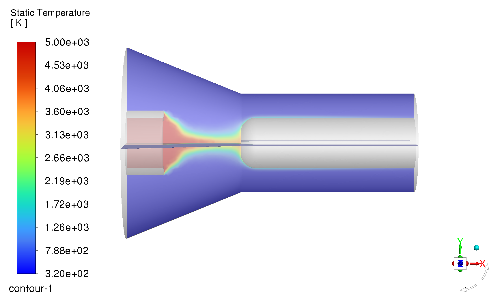
In this plot: The periodic BC has a UDS energy input of 124 kW and the fully revolved case has a UDS energy input of 2 MW. I did compare the plots with the same UDS values, however the flow fields still take on this shape.
Thank you again so much
-
November 20, 2024 at 9:55 am
Rob
Forum ModeratorThe 90 sector (top image) looks to have diverged - 5000K is the solver limiter so I'd not trust a result that's pinned to the limits. If the scalar (heat flux?) is for the whole device did you account for modelling a quarter of it?
I'm a little lost in the model description as interior and interface mean different things in Fluent but are commonly confused by translators. I am also not permitted to open/download anything so am limited to what I can see, and what is "public" knowledge.
-
November 20, 2024 at 3:05 pm
-
November 20, 2024 at 3:13 pm
Rob
Forum ModeratorAnd you've sorted out the mass flow for the sector? If so I'd expect the temperature field to also make sense.
The only oddity is having two zone 17 for periodic. It's usual for Fluent to give everything a unique ID.
-
November 20, 2024 at 3:39 pm
zoelle.wong
SubscriberYes - mass flow sector is sorted out. Without the heat sources for both the periodic and fully-revolved cases, the results match. I'm not sure if its a boundary condition problem if my cold flow cases match :(
to make the periodic interfaces, I first separated the domain, then created the periodic interfaces.
-
November 20, 2024 at 3:57 pm
Rob
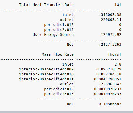
Forum ModeratorIn which case it should be fine. However, if the temperature is pinned to 5000K there's something not working right. How do the energy fluxes look in each case?
-
November 20, 2024 at 4:04 pm
-
November 20, 2024 at 4:12 pm
Rob
Forum ModeratorCheck inlets, outlets & walls. That should also pick up the source term(s).
-
November 20, 2024 at 4:16 pm
-
November 20, 2024 at 4:25 pm
Rob
Forum ModeratorEnergy needs to be 1e-6 or so, and that's covered in the Fluent courses in Learning. But you're only about 2% out on the balance. Mass balance is more of a concern.
-
November 20, 2024 at 4:41 pm
zoelle.wong
Subscriberyes.. my outlet BC is a pressure outlet. I've also tried enforcing "no-reversed" flow as a sanity check as the difference is happening between the inlet/outlet
-
November 20, 2024 at 4:43 pm
Rob
Forum ModeratorNo reversed flow really ought to be hidden in the TUI. Unless you know why you're using it, don't.
-
November 20, 2024 at 4:52 pm
zoelle.wong
SubscriberHaha good to know - thank you so much for trying to troubleshoot this with me.
-
- You must be logged in to reply to this topic.


-
4929
-
1638
-
1386
-
1242
-
1021

© 2026 Copyright ANSYS, Inc. All rights reserved.

