TAGGED: dynamic-mesh
-
-
November 14, 2023 at 2:54 am
Nate K.
SubscriberHello Forum,
I am looking for help regarding no flow through the inner domain of my 2D vertical axis wind turbine modeled in Fluent with 6DOF. Last time I did a similar model / simulation (sliding mesh) and under boundary conditions in Fluent interfaces where automatically created. Here, in the current model, this is not the case. I believe this is my issue with no flow through the inner domain, but I am not certain and not sure how to fix it. Can anyone help?
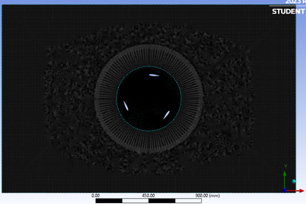
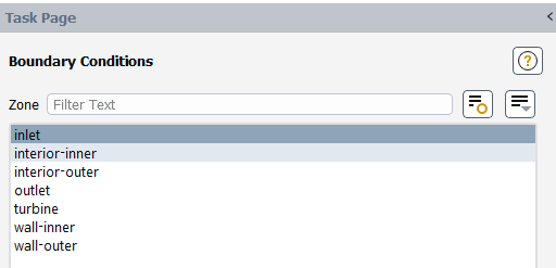
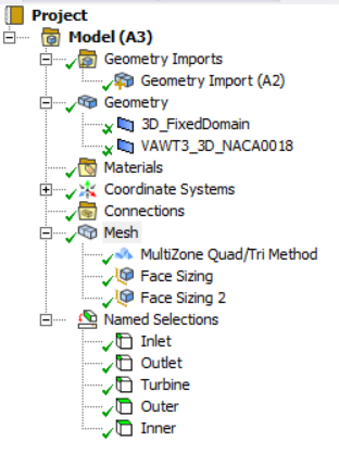
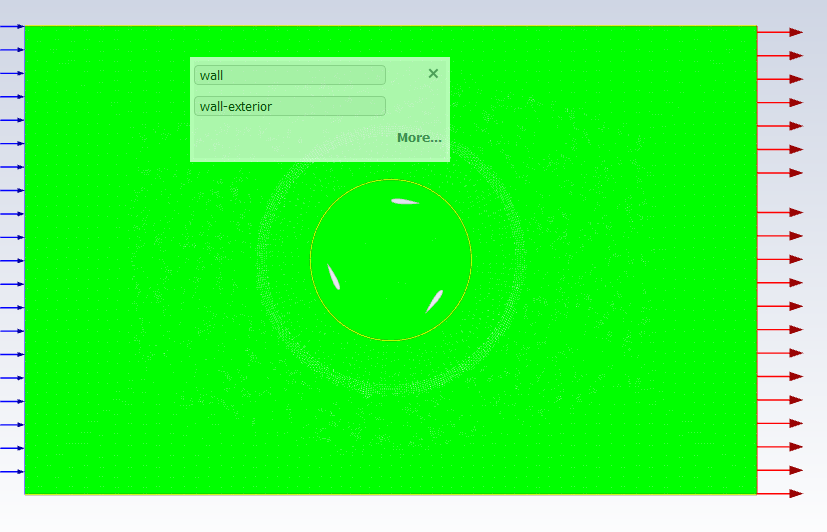
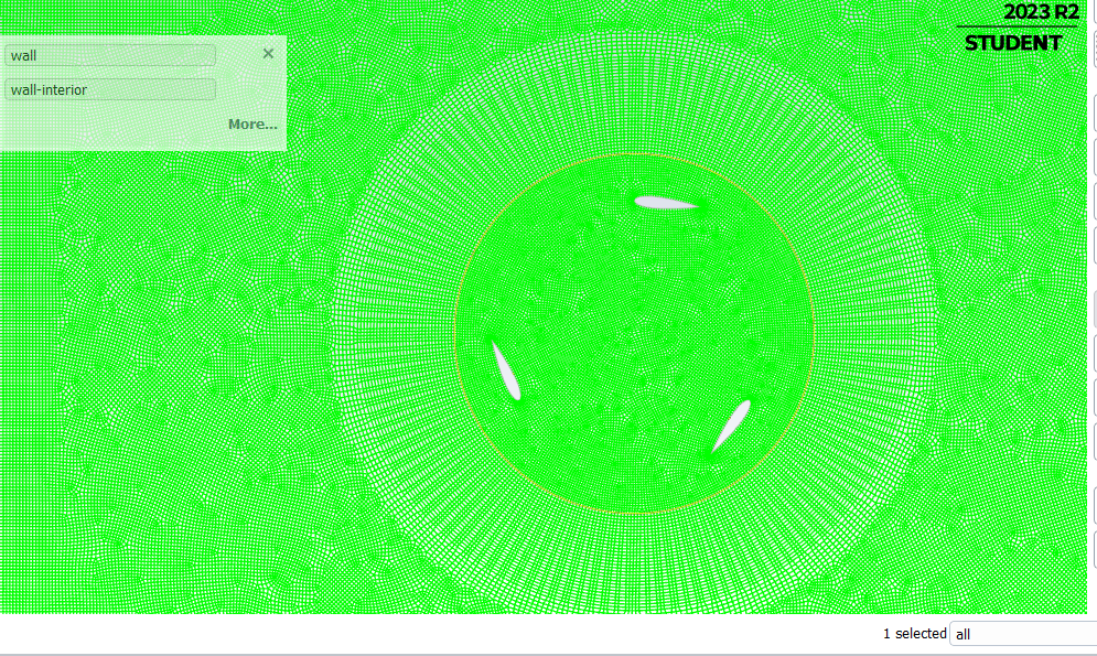
Attached are pics including the velocity contours showing no flow in inner domain, geometry, mesh, boundary conditions present, and Fluent Mesh model tree.
Thanks,
Nate -
November 14, 2023 at 2:22 pm
Federico
Ansys EmployeeYou need to create the Mesh interfaces in Fluent to convert these zones from type Wall to Interior.
-
November 14, 2023 at 5:17 pm
Nate K.
Subscriber... alright, the way I understand it the zone "wall-inner", which is the circle slightly outward around the turbine (the boarder of the no-flow through area that I want to fix), needs to changed to interior. However, when I try to do this, I am not given the option to change to interior (it is not on the list of available options). In other words, when creating the interface, I have to choose two boundary zones and so I chose wall-inner and wall-outer to create the zone but changing to interior was not available. Same for choosing wall-inner and turbine to create the zone... no interior option available... any insight by any chance?
-
-
November 14, 2023 at 5:41 pm
Federico
Ansys EmployeeYou should have two zones on either side of the circle highlighted in blue in your 3rd screenshot. If you don't, you may have to "slit" the single face zone in Fluent. You can do this with the following TUI command: define/boundary-conditions/modify-zones/slit-face-zone [id or name of face zone, right now it seems like you called it "wall-inner"]. Do the same thing if "wall-inner" is a coupled wall/shadow.
Once you have 2 faces zones on either side of the blue line, make sure you have the 1 to 1 pairing enabled (this should be default). In the console, enter define/mesh-interfaces/one-to-one-pairing? yes
Then, to create the mesh interface, go to Domain > Interfaces > Mesh... select the two face zones making up the interface. If the regions on either side of this interface are both of type Fluid, the interface will be changed to type Interior automatically.
-
November 14, 2023 at 5:58 pm
Nate K.
Subscriber... thanks, I will try that. But first, how do I enter the TUI system to input the command? Also, if I were to change the geometry so that that Fluent automatically creates two face zones on both sides of the circle, what should I change? Would be good to know for future models...
-
November 14, 2023 at 6:03 pm
Federico
Ansys EmployeeThe TUI is accessed via the console in Fluent. Just click in it and press Enter to start typing.
To have 2 face zones on both sides of the circle, you can set a named selection on the face for each cell zone. Fluent should then recognize this.
-
November 14, 2023 at 6:08 pm
Nate K.
Subscriber...thanks... and hmmm.. I did that.. you can see both named selections on the last pic above... "inner" and "outer" are both face zones for faces on both sides of the circle... any other ideas by any chance?
-
November 14, 2023 at 6:12 pm
Federico
Ansys EmployeeSo you are just left with creating the mesh interface. Did you do that?
-
-
November 14, 2023 at 6:11 pm
Nate K.
Subscriber... yeah so the question seems to be why is Fluent making the circle line a wall zone instead of two face zones on either side...
-
November 14, 2023 at 6:13 pm
Federico
Ansys EmployeeBecause you have a non-conformal mesh, the default boundary type will be a wall. Once you create the mesh-interface, interior-type is allowed.
-
November 14, 2023 at 6:28 pm
-
November 14, 2023 at 7:32 pm
Federico
Ansys EmployeePlease read my reply carefully. you don't have to use the slit command since you already have the face zones on either side.
-
November 14, 2023 at 7:49 pm
Nate K.
SubscriberI do not have two face zones on either side... rather, I have two named selections for either side. And despite having two face named selections, Fluent did not create two zones of these... rather it created a wall zone, as mentioned earlier. I cannot create the mesh interface if the two face zones are not created / available to choose from.. as mentioned previously.
You mentioned if the face zones are not available, that I could use the TUI code to create them.. so that is what I did but got the error seen in the pic above... -
November 15, 2023 at 11:11 pm
Nate K.
SubscriberAny further thoughts to potentially help by any chance? If not, do you know if there is a way to tag Ansys support engineers to this post at the current standing for further help?
-
November 16, 2023 at 1:29 pm
Federico
Ansys EmployeeMeshing does not allow to define Named Selection on overlapping zones, so it seems to me that you do have two face zones. This is also highlighted by the fact that you have "wall-inner" and "wall-outer".
What method are you using for mesh interface creation? Is it one-to-one pairing? Use the following command to set it accordingly: define/mesh-interfaces/one-to-one-pairing? yes
Once you have set this method, you should be able to create the mesh interface.
-
November 16, 2023 at 6:39 pm
Nate K.
SubscriberThanks for replying back.
I am simply going to "mesh interfaces" to try and create an interface. However, when going there there is no option to choose any face zones ... there is none listed. There is only the wall zones ("wall-inner" and "wall-outer" which I did not create these two directly... and then there is "turbine"). I have inserted the command you suggested, but nothing has changed. See pic for list of available zones to choose from. By the way, and perhaps you know this, but "wall-inner" is the inner circle -- the circumferential path -- and "wall-outer" is the upper and lower walls of the outer domain.
Seems I need to chage something in the geometry so that Fluent will then automatically create the interface I need / makes the inner circle not a wall, but I am not sure what to change. And/or perhaps there is settings to change in fluent but I am not sure... any other ideas would be appreciated if able... -
November 17, 2023 at 1:36 pm
Federico
Ansys EmployeeApologies, but we might not be clear on what is what. Earlier you wrote: "you can see both named selections on the last pic above... "inner" and "outer" are both face zones for faces on both sides of the circle..."
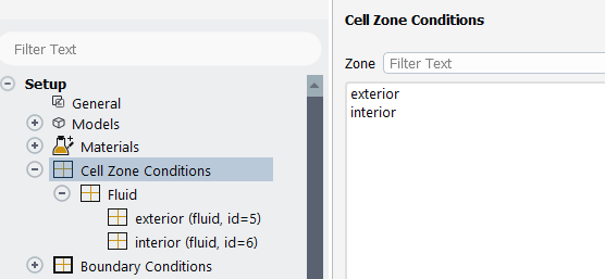
Can you show exactly what is wall-inner and what is wall-outer? Also, can you show your fluid cell zones? You should have 1 for the rotating domain, and another for the fixed domain.
-
November 17, 2023 at 6:36 pm
Nate K.
SubscriberThanks for getting back.
What I was saying was in response to you saying, "To have 2 face zones on both sides of the circle, you can set a named selection on the face for each cell zone. Fluent should then recognize this."... then I said "you can see both named selections on the last pic above... "inner" and "outer" are both face zones for faces on both sides of the circle"... what I should have said was the named selections "inner" and "outer" represent the faces which I want Fluent to make zones out of (zones to be). Why Fluent doesnt make the zones with the named selections as is would be a good thing to know (perhaps easier to just changed the geometry / mesh settings?), and as you said Fluent should recognize the named selections and make the zones... but yes, I said they are both face zones in error... kingly ignore that...all else is accurate.
I did not create "wall-inner" and "wall-outer" myself and am not sure where to see them exactly... however, when clicking on areas and lines in the displayed mesh in Fluent a text box does comes up with similar wording which I think is equivalent (e.g. "wall-exterior")...
1) First pic "wall-exterior" are the upper and lower walls to the outer domain and both are highlighted but hard to see here (my understanding "walls" here are applied automatically by Fluent via symmetry... I did not have named selections of these lines...after inlet and outlet are assigned).
2) In the second pic, "wall-interior" is the inner circle... how to I say this.. it is the ring... the red circle, not the face, which radius is slightly further out from the woud-be turbine radius... the only red circle. And of course this is the wall that the fluid is not entering during simulation.
3) Third pic shows the fluid cell zones... one exterior and one interior.
-
-
-
November 17, 2023 at 8:13 pm
Federico
Ansys EmployeeOk, understood about Wall-exterior and Wall-interior. Do you also have wall-inner and outer? Or have these names changed to the screenshots above? Now for the cell zones, I assume that interior is everything inside of Wall-interior and exterior is everything outside of this. Correct?
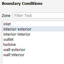
Now, can you show me a screenshot of all the existing boundaries, as you have for Cell zones?
-
November 17, 2023 at 10:44 pm
Nate K.
Subscriber...actually, when I click on the mesh in Fluent inside the inner circle it calls this space "interior-interior", and clicking outside the circle it is "interior-exterior" (and these namings are also seen in the existing boundary zones pic sent today)... for whatever that is worth. The named selections I named as mentioned in the previous message (all inside the circle is interior and all outside is exterior).
-
November 20, 2023 at 10:14 pm
Nate K.
SubscriberNo offense to you Frederico, but by any chance is anyone else able to help... any Ansys Tech Engineers or anyone else? Of course, Frederico, I appreciate your help and hope you can still help me, but tomorrow marks a week since first posting the issue which I really need to solve. My school project needs to progess.
Do Ansys engineers get notices of each reply of each post here in the Learning Forum (are Ansys Engineers following updates in each post?)? Or do I need to create a new post? I just need help with why a wall is being created in-between my two fluid flow areas... I have tried all evident options within Fluent settings and scoured the internet but to no avail... any help from anyone would be greatly appreciated. -
November 20, 2023 at 10:18 pm
Nate K.
Subscriber...oh by the way, Fredrico, if you are reading this, check out my reply I made on Friday starting with "Shoot, and yes...", as it appears I did not reply to you but rather to the post itself. You would not have recieved a notice for it, anyways, I believe.
-
-
November 17, 2023 at 10:38 pm
Nate K.
SubscriberShoot, and yes, you are correct, it looks like my screenshots from today are from a different file with geometry labeled "exterior" and "interior" instead of "inner" and "outer"... sorry for the confusion... it does make sense now... so we can forget the "inner" and "outer" and just sitck with "exterior" and "interior" and all screenshots from today.
Cell zones, yes that is correct, all inside wall-interior is interior and all outside this is exterior.
Absolutely, here is a screenshot of existing boundaries: -
November 21, 2023 at 3:12 pm
Federico
Ansys EmployeeUse TUI command to slit wall-interior
define/boundary-conditions/modify-zones/slit-face-zone wall-interior
By default, Fluent used one-to-one pairing for Mesh interface creation, but to be sure you can enter define/mesh-interfaces/one-to-one-pairing? yes
Go to Mesh > Interfaces and create an interface between wall-interior and wall-interior-slit. You should now find that the mesh interface is set to type Interior.
-
November 21, 2023 at 6:55 pm
Nate K.
SubscriberThanks for replying.
I have entered the TUI command “define/boundary-conditions/modify-zones/slit-face-zone wall-interior” but got the error message in first pic.
Also, perhaps the error has to do with this, and this is something I just discovered: the red circle / wall is actually defined as having two sides: “wall-interior” and “wall-exterior”. I have taken a screenshot displaying this text… clicking on each side of that narrow red circle — right on the red circle itself but teeny bit to one side — leads to the ”wall-interior” and “wall-exterior”… so if the red line was a wall then if I click on the outside edge of the wall I get “wall-interior” and clicking on inner edge gives “wall-exterior”… yes, it is backwards… inner side actually displayes “wall-exterior”… not sure the backwards part matters, sharing for whatever it’s worth.-
November 21, 2023 at 7:26 pm
Federico
Ansys EmployeeIf there are 2 sides, then you should be able to create a Mesh Interface selecting wall-interior and wall-exterior.
-
November 23, 2023 at 9:20 pm
Federico
Ansys Employeeas per my 2nd reponse on Nov. 14th :)
-
November 23, 2023 at 9:58 pm
Nate K.
SubscriberHmm... I made a reply the other day but apparently it did not get sent... bummer, well here is a similar reply:
That worked! Excellent. And looking back I see the issue, and just to summarize our journey here for you and others that may have a similar issue in the future... in Fluent, in the mesh "map" (not sure the name), when clicking on the tiny red circle / line / that is surrounds the inner domain, it lists it as "wall-interior" and when clicking on the upper and lower edges of the outer domain, Fluent mesh calls these two "wall-exterior"....fine, makes sense. However, the confusion was, and since I was not aware, that I had to click on both edges of that TEENY red circle -- right on the edge of the line itself (and this is not an easy task... especially when you are not aware to do so... you have to zoom in greatly and keep moving / clicking till you get them) -- to see if there was two sides... and indeed there was two sides. Knowing this I could then choose them both -- they were both listed in the list of boundary zones afterall -- to make the interface. So not knowing to click on both edges of the TEENY circle, and since clicking on the circle and seeing "wall-interior" and then clicking on the upper and lower walls to the outer domain and seeing "wall-exterior", logically one would think, ok, two completely different sets of walls being in completely different locations so I definitely cannot -- nor do I want to -- make an iterface between them... so I didnt even try. Skip forward and through all the talking with you, and playing around lots with clicking in the mesh etc, and eventually I found out there was two sides to the inner circle / wall.
Lesson: a wall between two face zones will have two sides.
Also, kinda still wondering, and kinda a rhetorical question [unless you know and want to answer! :-)] why the heck would Fluent make the upper and lower edges to the outer domain named the same and one side of the interior domain wall? Seems like when making the interface as I did that it would somehow also apply to the upper and lower walls of the outer domain, no? Maybe I still have not done something correct... well, at least I have flow inside the inner domain now...
Thanks, Federico, for your help so far... I could not have done it without you!
-
-
-
November 24, 2023 at 3:41 pm
Federico
Ansys EmployeeSo the best way to avoid this confusion is simply to display your boundaries one at a time in Fluent and inspect them in the graphics window. This way you would have seen right away what each of you boundaries look like. Something like this:
In your case, you created the mesh in Ansys Meshing and brought it to Fluent. First, I would recommend using Fluent Meshing with Watertight Geometry workflow, as it has a task that explicitly asks you if you want to make Fluid-Fluid interfaces of type "internal". In your case, as you bring the mesh from Ansys Meshing, Fluent has some interpretation to do for any un-named zones and assign them a boundary type. I'm assuming that you named the cell zones but not the faces explicitly. Fluent then just assigned the remaining faces as type wall, which caused this confusion.
I hope this helps!
-
November 28, 2023 at 4:10 am
Nate K.
Subscriber...great, I will use the "mesh display" next time... that does help. Thanks.
-
-
- The topic ‘No Flow Through Inner Domain — wind turbine’ is closed to new replies.


-
3492
-
1057
-
1051
-
955
-
932

© 2025 Copyright ANSYS, Inc. All rights reserved.


