TAGGED: interconnect
-
-
July 24, 2024 at 3:08 pm
sicli21
SubscriberHi,
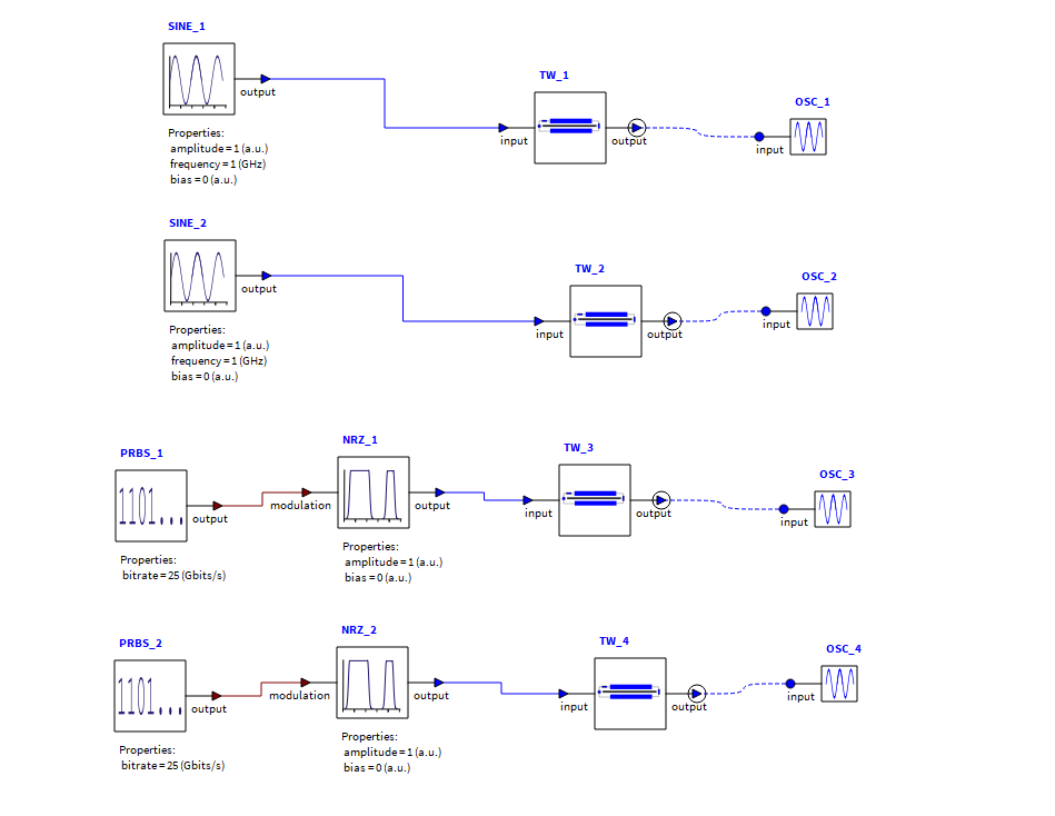
1.I have the following structure. I am applying Sine wave to Travelling wave electrode, however, I don't see the effect of changing TWE parameters like source-characteristic impedance. However, if I change my source to PRBS and NRZ, I see the effect of TWE parameters.
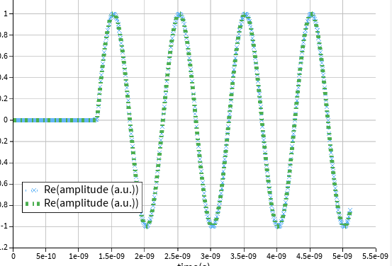
2. If I connect another Oscilloscope to input of TWE, I see there is a delay in the signal. For example, the oscilloscope traces are starting around 1.25e-9. Even if I make my TWE 1 nm, the delay is same. While in the oscilloscope at the input of TWE it starts from 0. What is the explanation of that ?
Kind regards
-
July 24, 2024 at 9:22 pm
Kyle
Ansys EmployeeHello,
- Which parameters are you changing? It's possible that they may only be having a small effect at the frequency of the sine wave. Also, keep in mind that the output of this element is not the voltage across the terminating impedance, it is the effective voltage experienced by the optical pulse as it travels through the modulator. Some expected results for transmission lines might not apply to this element. This page (and the included reference) have more information on this model: Traveling Wave Electrode (TW) - INTERCONNECT Element – Ansys Optics
- In a time domain simulation the frequency-dependent properties of this element are modelled with a finite impulse response digital filter. This digital filter includes an artificial delay, which is why you're seeing a delay in the output. In most cases this constant delay won't have an effect on the results of the simulation so it is generally ignored.
-
July 26, 2024 at 4:33 pm
-
August 1, 2024 at 10:53 pm
Kyle
Ansys EmployeeI would recommend connecting an Electrical Network Analyzer with the "analysis type" property set to "impulse response" to the TWE element while changing the properties to see the effect on the element. This will give you the entire spectrum of the element's reponse instead of just the properties at one frequency, which is what you get with the sine wave source. This will give you a better understanding of what changing each of the properties does to the element's response.
As for the different number of samples, this is normal. The signals generated by each of the sources could go through different delays, so they may not have perfect overlap in time at each of the elements. This results in fewer data points recorded by the monitor.
-
- The topic ‘No Filtering Effect of Travelling Wave Electrode with Sine Wave’ is closed to new replies.


-
3487
-
1057
-
1051
-
945
-
917

© 2025 Copyright ANSYS, Inc. All rights reserved.


