TAGGED: convergence, mechanical, newton-raphson-residuals
-
-
January 9, 2025 at 2:46 pmlvelasquezSubscriber
Hey,
Are the Newton-Raphson Residuals only available when the simulations fails to converge? Like, if I already see it´s taking too long in a substep can I just stop the simulation and check de residuals anyways.
I have a simulation (static, non-linear, nothing too complex trust me) that at some point it wont converge, does a bisection, converge, does a bisection, converge, bisection, and so on for a looooong time having time steps of 0.2E+2. I can leave it overnight, but waiting 3+ hours for something I know it will fail... not my first option.
Thanks.
-
January 9, 2025 at 7:30 pmpeteroznewmanSubscriber
The convergence chart that shows the maximum value of Newton Raphson residual versus iteration number is always shown, but what you want to see to is a plot of the location of the maximum value of NR residual on the mesh. Knowing the location allows you to add a mesh control at that location to improve the element quality and usually to use smaller elements to help the convergence. The plot is not automatically created, you need to turn it on by typing a number larger than 0 on Netwon Raphson Resuidual line under the Solution Information folder. Then after a Solve, there will be as many plots to look at as the number you typed. Each plot is for the last few iterations.
There are other things to do to help convergence. Under Analysis Settings, turn on Automatic Time Stepping, then under that set the Initial and Minimum substeps to a value such as 10 and the Maximum Substeps to 1000. You have to do that for each step in the solution sequence.
-
January 13, 2025 at 3:30 pmlvelasquezSubscriber
Hello Peter,
Thanks for the link and the information. I took a look to the NR residuals and saw the problematic area; but what it´s interesting though is the behaviour of other element. I know it´s scaled and exaregated but it´s weird this is happening.Â
For context: I´m simulating this system, which is hold by three bolts. I apply a force in the inner face of the square element and "fix" it by the thin element. I removed the Bolt pretension to simply the simulation, but I´m not getting anywhere.
Here are the contacts:
-
January 14, 2025 at 11:51 ampeteroznewmanSubscriber
Under Analysis Settings, turn on Large Deflection. Plot the deformation at True Scale 1.0
It looks like you have cut this geometry out to analyze. If that is the case, you should use a Symmetry boundary condition. Please show the full geometry and explain how it connects to ground. I do not think that a Frictonless Support is an accurate way to support this structure.
-
January 14, 2025 at 2:34 pmlvelasquezSubscriber
Hello Peter,
Yes, large deflections are on. At True Scale it´s bearly visible, displacement of 4.1E-2 mm (max).Â
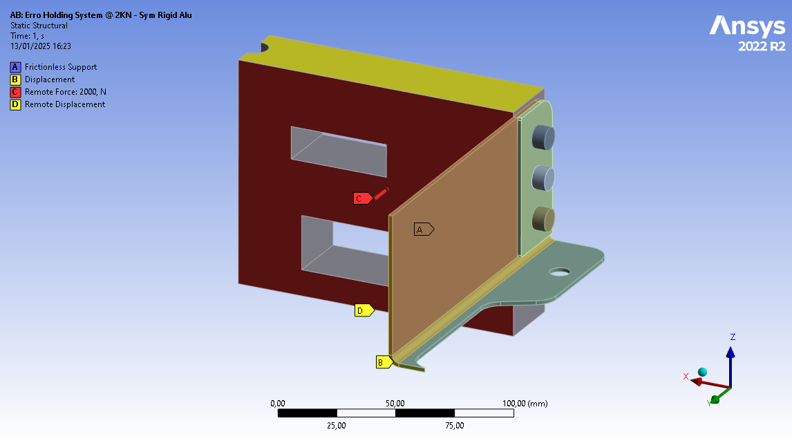
Correct, I did cut the geometry in two parts: the first, where the symmetry boundary is ON it´s in the X axis (for the grey body), it´s made of plastic. The second cut was in the orange element (aluminium), this element is originally 1 meter long, which I reduced to 150mm because the stress profile stays the same along this path. Imagine the whole system its mirrored in both X and Y directions, I´m simulating a quarter of the system.
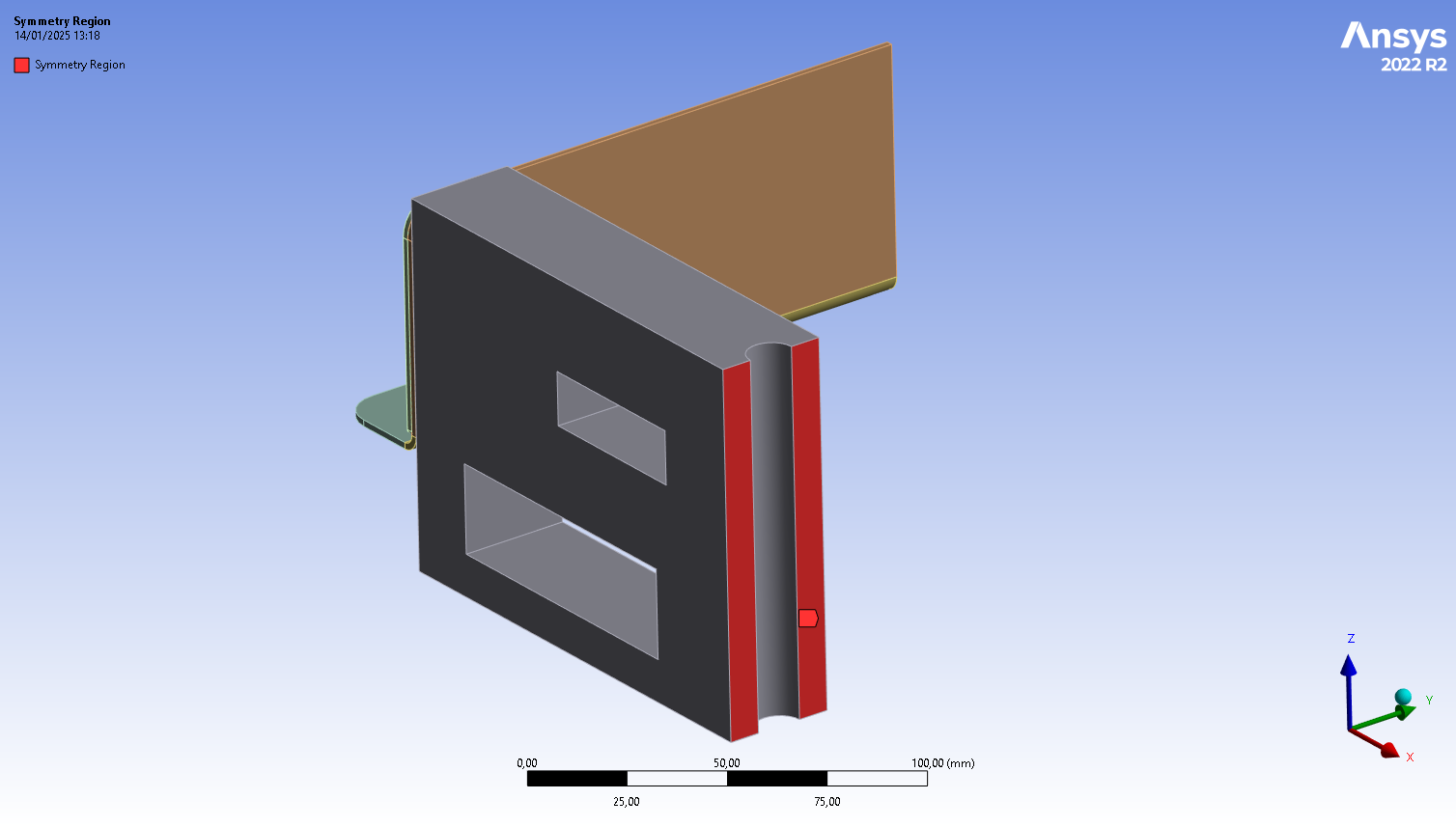
This components hold a series of elements to be compressed at a certain "clamping force", so the simulation is for the post-compressed state. So, the force is applied in the entire inner face of the gray body in -Y direction and I fixed the thin element in the cross side. Now the force alone will deform the element like this:
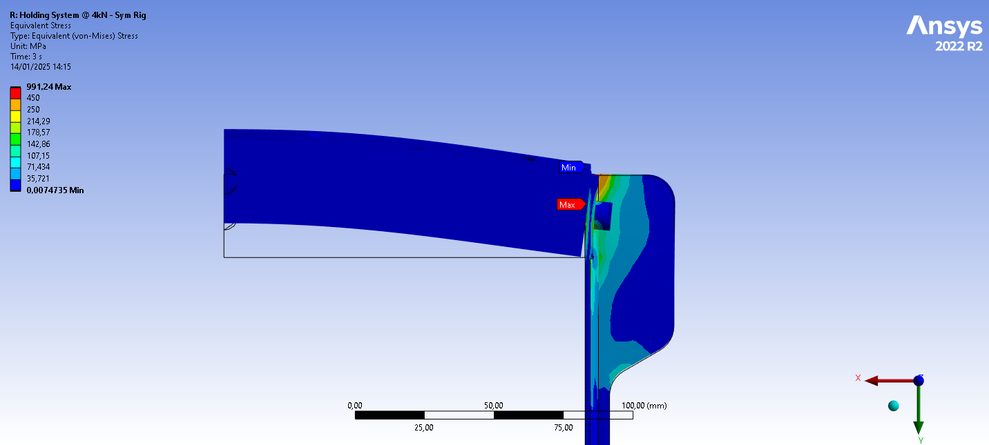
This behaviour it´s not true due to the fact that the elements inside are infinitely more rigid so they will evenly apply the force, so I used a remote displacement in the upper and lower faces of the grey body to limit all DOF except the Y direction. The frictionless supports comes from the fact that there are elements inside the system, so it can´t deflect to the inside (thinking about it, this can be eliminated since the thin element is mostly in tension when realized I needed to fixed the motion of the solid body).
And for "how it connects to ground" well, I thought fixing the cross section of the thin body was enough to have a ground per se, I have weak springs on just in case.
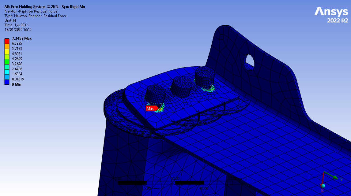
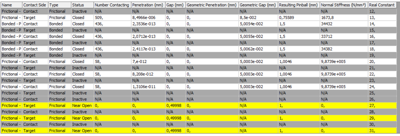
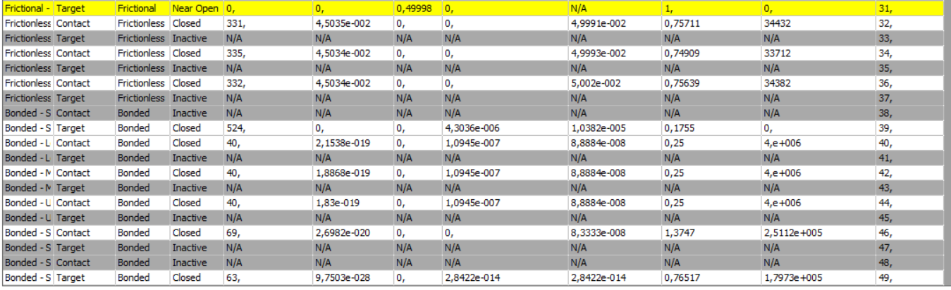
I reduced the force from 2,000 N to 1 N just to try, interestedly enough the simulation converged (so no NR residuals), but the explosion of the elements is there, it happens right at the beginning. I added an off-set to the contacts to pass from NEAR OPEN to CLOSED, this made a tinny penetration (about 4.5E-2 mm) so I´m thinking this "explosion" of the holes might be from early penetration; I changed to "adjust to touch" and I´ll see what happens.Â
Thanks.
Â
Â
Â
Â
-
January 14, 2025 at 4:45 pmpeteroznewmanSubscriber
The structure you have meshed has six rigid body motions that must be constrained. The faces with symmetry in the X axis create 3 constraints.
You could use symmetry in the Y axis on the cut face of the thin sheet body. Symmetry in X and Y make a total of 5 constraints. The structure is still free to have rigid body motion along the Z axis. Instead of symmetry in the Y axis on the cut face of the thin sheet body, you could use a Displacement and set Y and Z at 0 and leave X Free.
You mentioned that the inside face of the thin sheet would push against components inside the frame that are not modelled. That is where you initially used Frictionless Support. A better choice for that face is Compression Only support. That allows the sheet to "lift off" the plane defined by the inner face, but not penetrate the plane. One caution is that this support makes the problem a non-linear solution so solve time may be increased.
What creates the force on the grey block? Is it another part? Ideally you would add that part to the model, constrain it with a translational joint to ground, add a joint load to apply the force and add a Frictional Contact between that added part and the grey block.
-
January 15, 2025 at 11:23 amlvelasquezSubscriber
Hi Peter,
I have what you suggest, except having X free in the cross section of the thin element; I had it fixed. I´ll check if that is doing something. Yeah, I´ve read that Compression Only adds some complexity and therefore the time increases. I´ll have it in mind for future simulations.
The elements inside are rectangular batteries that have a comprenssible protective layer between each other. I was thinking something similar to what you suggest, I thought of adding a thin block, defining it as RIGID (so no additional elements) and apply the force via remote force and not directly to the grey element. But the use of translational joint might be better so I don´t have more BC to restrict DOF.
Â
This might be off topic, but what is your opinion regarding the clearance between solids in CAD for FEA, specially with pins and holes? Like, with little to no clearance you need refined mesh to avoid element penetration. In the other side, too much clearance needs additional preprocessing time to get ANSYS close the contacts.Â
Â
Thanks
-
January 15, 2025 at 1:36 pmpeteroznewmanSubscriber
Pins in holes are generally for locating parts so there is very little clearance. In that case, I would model them with zero clearance.
Bolt shanks are generally in clearance holes. If there are no pins to locate the parts, the bolt pretension and the friction between the bolt head and the plate should be large enough to prevent slipping due to shear loads or to prevent a gap opening due to axial loads. In that case, you are not relying on the side of the hole touching the shank.
If you need a pin in a hole to have clearance and you know the load direction, the parts can be moved in CAD to make them tangent on the contact side. It would be best to have smaller elements around the hole and on the pin to get accurate stresses.
It is possible to leave the pin in the center of the hole, which might be convienient if you have lots of pin/holes. There is a setting in the contact definition that makes convergence easier to achive because it puts a damper on the motion when the plate slides to close the clearance.
-
- You must be logged in to reply to this topic.
- How to apply Compression-only Support?
- At least one body has been found to have only 1 element in at least 2 directions
- Error when opening saved Workbench project
- Geometric stiffness matrix for solid elements
- Script Error Code:800a000d
- Timestep range set for animation export
- Image to file in Mechanical is bugged and does not show text
- Elastic limit load, Elastic-plastic limit load
- BackGround Color
- Element has excessive thickness change, distortion, is turning inside out
-
1642
-
618
-
599
-
591
-
366
© 2025 Copyright ANSYS, Inc. All rights reserved.