TAGGED: -LS-DYNA-run-time, explicit, impact
-
-
October 14, 2024 at 10:25 am
j2001
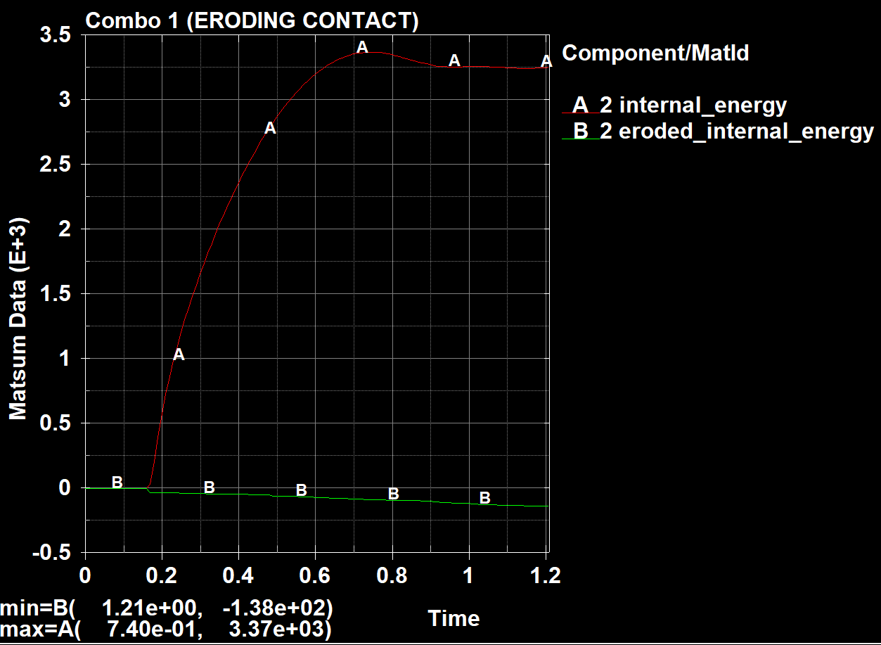
SubscriberHi everyone, just wanted to check, is negative eroded internal energy in an impact test normal? For a couple of other models that I've done, the eroded internal energy is positive. I'm not sure if it's something to do with the surface A or surface B definition, but the context is that this is for a deformable projectile and a rigid target, where the erosion happens in the projectile, and in my other model it's a deformable target. I've also turned ENMASS on, but the material model and contact definition has erosion criteria turned on. Just wondering if it starting with kinetic energy vs without kinetic energy dictates whether the eroded IE is positive or negative? Thanks.
-
October 15, 2024 at 11:33 pm
Reno Genest
Ansys EmployeeHello Jordan,
You mean negative eroded internal energy and not eroding contact energy correct?
Do you have shell elements in your model? Negative internal energy indicates a problem with the model. See the following link:
Internal Energy — Welcome to the LS-DYNA support site
From our knowledge database: "If you subtract "eroded internal energy" from "internal energy", you have the internal energy of elements which remain in the simulation."
So, the eroded internal energy is the internal energy of elements that have failed and got deleted (eroded) from the simulation. This means that the internal energy just before these elements were deleted was negative which is not correct.
If you remove the failure criteria in your model, do you get negative internal energy for certain parts? Check internal energy by part using the matsum database.
You can try to add *DAMPING_PART_STIFFNESS to the model and see if you get rid of the negative internal energy.
Which version of LS-DYNA are you using? Have you tried with the latest version?
Also, have you tried SMP vs MPP?
You can review the crash guidelines and see if you can solve the problem:
https://ftp.lstc.com/anonymous/outgoing/support/PRESENTATIONS/Crash_Guidelines.pdf
Let me know how it goes.
Reno.
-
October 16, 2024 at 6:47 pm
j2001
SubscriberHi Reno,
Yes, you're right, I meant negative eroded internal energy.
Regarding the context of the model, I have no shell elements in the model, only a rectangular deformable (MAT_143) wood projectile striking a rigid cylindrical target attached to a spring, both using solid elements,. The model is supposed to be measuring the contribution of spring stiffness + "lumped mass" inertia to overall contact force history. I've added SLDTHK offsets to the ERODING_SURFACE_TO_SURFACE contact, and I'm using SOFT = 2 since it's wood impacting on metal (and the meshes are a bit different since one is rectangular and the other is circular). I'm also using CONTACT_AUTOMATIC_SINGLE_SURFACE for the projectile self-contact, with SOFT = 1, with some adjustments to SOFSCL and SFSA in that contact definition. I've tried a lot of things from changing stiffnesses, changing the value of VDC, changing hourglass control parameters, to make it such that hourglass energy is low and interpenetrations aren't present. I've never been able to solve the negative eroded internal energy issue, however. A problem I had at the beginning was that the entire frontal layer of elements would erode upon impact, which is why I increased SLDTHK and penalty stiffness scale factors in the first place.
Also, that internal energy screenshot I attached originally was from MATSUM, of the projectile. I did find it strange that the total internal energy in MATSUM was lower than the internal energy without considering eroded energy.
If I turn off the erosion criteria for the material (IVOL = 0 for wood), I get an error termination after a short while (negative volume and out of range velocities), but the eroded internal energies that result from the few deletions that happen before that are still negative. Worth noting that the internal energies of the projectile that aren't deleted remain positive throughout the simulation, though. From what I can see, everything else looks fine but the eroded internal energy being negative really perplexes me, since I've used this same exact projectile to impact a deformable shell target, and the shell's eroded internal energy was positive while the projectile's eroded internal energy was sometimes very slightly positive and sometimes very slightly negative. In this solid-solid contact simulation it's consistently negative, however.
As for the version of LS-DYNA, I'm using R15.0.2 for the solver (it says smp_d_R15.0.2_.....), which should be quite recent as I downloaded that from the website earlier this year.
Since receiving this, I've tried:
- Setting DAMPING_PART_STIFFNESS to 0.2, to which I got the same results.
- Removing VDC
- Increasing VDC on the contact definition to a large number like 60
- Setting the self-contact definition back to default
- Scaling contact stiffness on the eroding contact definition
- Changing hourglass modes between 5 and 6, with varying QM parameters according to the crash guidelines file you attached
From which I got varying other results (like contact force or timestep) but energy was still increasingly negative the more elements eroded from the wood model. Is it something to do with the failures possibly being due to negative volume (negative volume causing negative internal energy)? Let me know your thoughts.
-
October 16, 2024 at 7:18 pm
Reno Genest
Ansys EmployeeHello,
It is possible that the negative eroded internal energy is caused by negative volume error. If you get negative volume or out-of-range forces or velocities error messages without a failure criteria, this indicates some degree of instabilities in your model. I would try to fix the negative volume and instability problem first and then try to activate element erosion again. Here are some tips to combat instability and negative volume errors:
- Make sure you have a good quality mesh. If the element quality is bad, you are more likely to have elements with high distortion and negative volume.
- Reduce the time safety factor (TSSFAC on *CONTROL_TIMESTEP) from 0.9 to 0.66. This can be effective especially if the impact is very fast.
- Increase the d3plot output frequency and animate the results to see what is happening and what triggers the instability.
Also, I would try to remove the *CONTACT_AUTOMATIC_SINGLE_SURFACE for now. Having redundant contacts is not recommended.
You will find more information on negative volume and instabilities here:
https://ftp.lstc.com/anonymous/outgoing/support/FAQ/negative_volume_in_brick_element.tips
https://ftp.lstc.com/anonymous/outgoing/support/FAQ/instability.tips
https://lsdyna.ansys.com/have-you-any-tips-on-how-to-to-combat-instability/
https://lsdyna.ansys.com/negative-volumes-in-brick-elements/
Let me know how it goes.
Reno.
-
October 16, 2024 at 7:53 pm
j2001
SubscriberHi,
Thanks for your reply. I found that if I left everything else and increased SLSFAC, it caused the eroded internal energy to become positive. This also massively increased forces between the interfaces, as well as hourglass energy and reduced timestep and hence blew up runtime by a large margin. I'd imagine this same effect occurs when I reduce timestep by a similarly large margin, but I found that this way it allows the simulation to still control the timestep through the stability criteria considerations. Would this be a right way to go about solving this issue?
I also noticed that the resultant forces at the projectile/target interface are now different (as in, the red and green lines are both very slightly visible when I activate them in RCFORC). Is this normal?
Thanks
-
October 16, 2024 at 8:19 pm
Reno Genest
Ansys EmployeeHello,
Which value did you use for SLSFAC? By increasing SLSFAC (contact stiffness), the timestep will change as well. Here is more information from the LS-DYNA User Manual Vol I:
"Time Step Scale Factor TSSFAC. During the solution we loop through the
elements and determine a new time step size by taking the minimum value over
all elements:
ΔW +T = TSSFAC × min{ΔWT, ΔW,, . . . , ΔWà}
where N is the number of elements. The time step size roughly corresponds to
the transient time of an acoustic wave through an element using the shortest
characteristic distance. For stability reasons the scale factor TSSFAC should be
set to a value less than 1.0. The default value of TSSFAC is as follows:
a) If contacts are present, and SLSFAC is specified in CONTROL_CONTACT,
then
TSSFAC = }
0.333 for SLSFAC ≥ 9.
0.667 for 1.≤ SLSFAC < 9."So, if you used SLSFAC between 1 and 9, then TSSFAC will be equal to 0.667. So, this would have a similar effect to setting TSSFAC=0.66. Now, maybe the contact stiffness has an impact here.
I would try with SLSFAC set as before and set TSSFAC=0.667 and see if it also fix the problem. If not, then the contact stiffness plays a role.
I don't understand what you mean by red and green lines in the RCFORC. Could you post the graph?
Reno.
-
October 17, 2024 at 1:08 pm
j2001
SubscriberHi,
Sorry, I meant the RCFORC results for SURFA and SURFB were slightly different at some times when I changed the SLSFAC factor. Additionally, shortly after the seemingly positive eroded internal energy, it dips and becomes negative again.
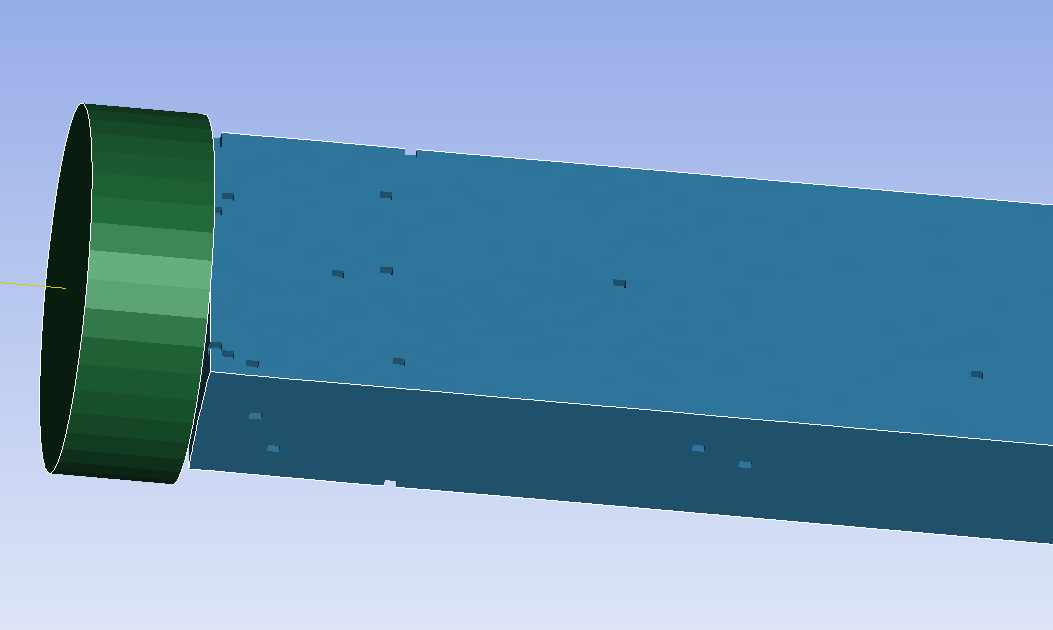
I've also since then tried varying combinations of SLSFAC, TSSFAC, SFSA and SFSB. It seems SFSA and SFSB don't change my timestep at all, but the higher I set them, the more unstable the model becomes (ie total energy increases by >4%, negative contact energy, etc). The only times I find that there's no negative eroded internal energy is when the material behaves "softly", deflecting outwards when compression is experienced. Perhaps overstiff behaviour is present in my model? The element failures on the projectile can be seen below, in blue.
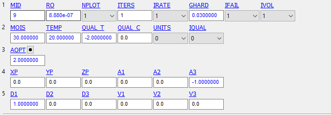
They appear in "Spots" away from the impact location, seemingly randomly. I have a feeling that the material is deleting them due to negative volume, because they're not failing normally. The wood material manual does say that when the elements perpendicular to the grain reach failure criteria, they don't fail unless they reach negative volume. Just in case, is there anything off about my material inputs for MAT 143?
I typically have IFAIL off, I just had it on in that screenshot for debugging, and it didn't eliminate the negative internal energies. I also set A3 in the negative Z axis because that's the direction my projectile is travelling, but I don't think that made a difference when I changed it either.
-
- You must be logged in to reply to this topic.


-
3487
-
1057
-
1051
-
955
-
922

© 2025 Copyright ANSYS, Inc. All rights reserved.


