-
-
November 23, 2023 at 10:13 am
Davide Parlato
SubscriberHi everyone,
I am running a two-way Fluent-Mechanical simulation of a shelf (100x3x200mm; xyz) immersed in a tank (300x500x300mm; xyz) filled with a liquid and a gas using VOF method. The tank is subject to the force of gravity and a harmonic force acting along the x-axis with a frequency f=2Hz. Since I wanted the liquid to be initialized with an angle of 10° I have created a region register with cylinder shape with the coordinates shown below. The other settings are shown below as well.
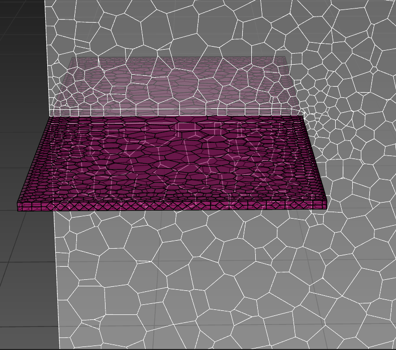
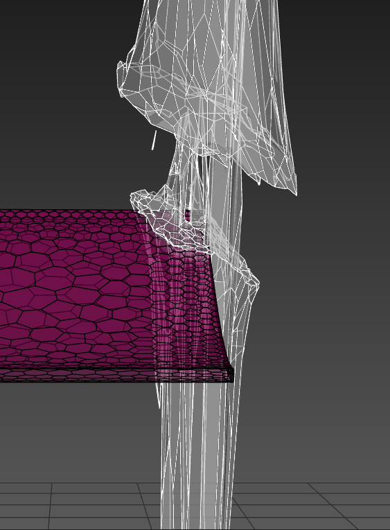
When I launch the analysis it stops at a certain time step for "Negative cell volume detected". I have tried to reduce the time-step but it stops even earlier in the simulation. Furthermore, looking at force report (from Fluent) and displacements report (from Mechanical) I have noticed that in the time step that leads to the error, the force and the displacements increase inexplicably and I am not understanding the reason if everything is going well until that time step. To visualize the cells with negative volume I have created a volume register and a iso-surface.- Mesh of the shelf and a plane in the middle of the tank at t=0
- Mesh of a plane in the middle of the tank at t=0
- Register region settings
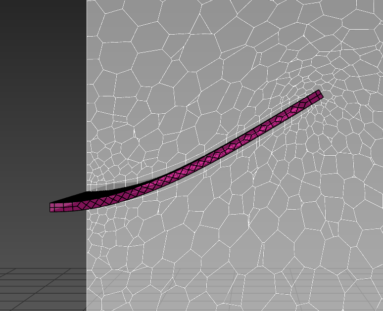
- Displacement of the shell at last time step
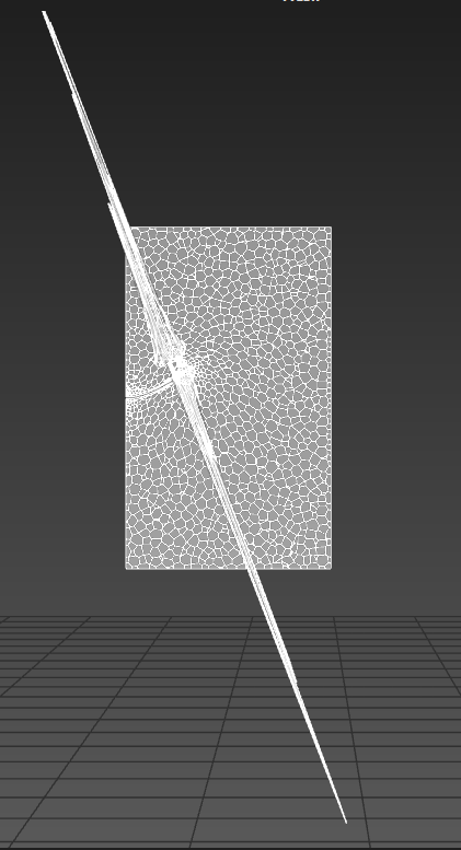
- Iso-surface with negative volume cells and a plane along the tank at last time step --> I think that the weird shape of the negative volume cells is due to the register region that I have created to patch the liquid region since it goes from the minimum coordinates and maximum coordinates that I have selected for the region register. I am not sure of this.
- Register region with tank and negative volume cells
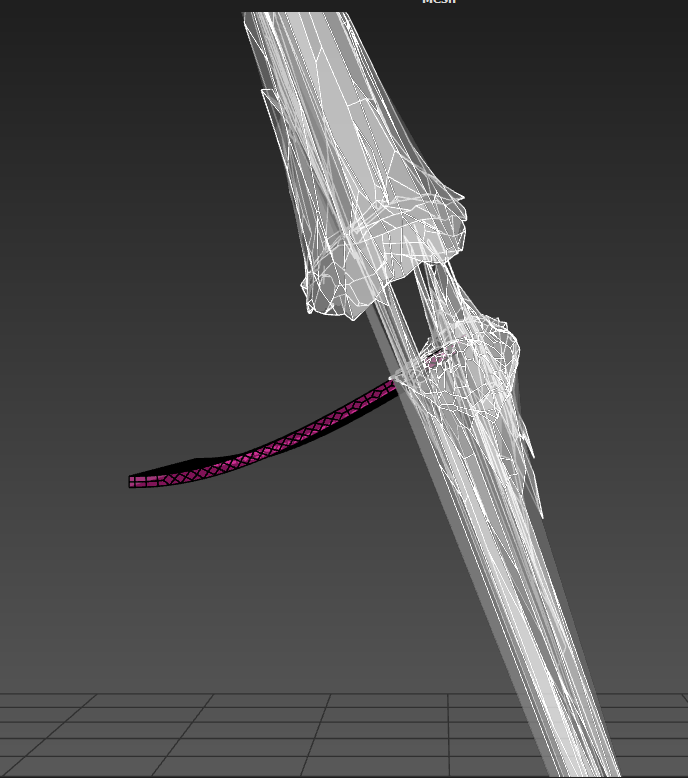
- Display of the shelf and negative volume cells at last time step pt.1
- Display of the shelf and negative volume cells al last time step pt.2
- Dynamic Mesh Settings: Smoothing (Diffusion method with Diffusion Parameter: 1.5) and Remeshing (Unified Remeshing).
Can anyone point me a solution or a way to understand what is failing during the analysis?
Feel free to ask any other information that you may need. Thanks in advance. -
November 23, 2023 at 2:15 pm
Federico
Ansys EmployeeAre you using compressible liquid in Fluent? Incompressible fluids can lead to pressure spikes which can cause issues with force calculations.
-
November 23, 2023 at 3:20 pm
Davide Parlato
SubscriberNo, I am using a incompressible fluid (cryogenic methane) since I have an operating pressure of 3bar. I can give it a try but theoretically I don't think that the density is changing remarkably (take in mind that I have turned off the energy equation).
-
November 23, 2023 at 4:07 pm
Federico
Ansys EmployeeRight, compressible liquid don't vary in density too much but it does make a difference for the solver. You may also try introducing Solution stabilization to your moving boundaries 12.6.9.8 Solution Stabilization for Dynamic Mesh Boundary Zones (ansys.com)
-
November 23, 2023 at 5:38 pm
Davide Parlato
SubscriberI will definitely give it a try. I have already introduced a coefficient-based solution stabilization for my dynamic mesh zone but actually you have brought up a doubt that I have. The only dynamic mesh zone that I have defined is the region that I have called “fsi” (which stand for fluid structure interface) (i.e the shelf) and I have set it as a “system coupling region“. Since that is the only region with dynamic mesh, is Fluent smoothing and remeshing only that zone? If yes, does that mean that when the shelf moves a lot (like in the pics), the cells of the plane (which is representative of the inner cells of the tank) close to the shelf are deformed without the possibility to smooth/remesh?
-
November 23, 2023 at 6:13 pm
Federico
Ansys EmployeeWould be best if you posted your screenshots directly on the post, as I cannot use your links.
To answer your question, it depends on the topology of your problem. Smoothing/Remeshing may occur on some adjacent zones to the FS-interface (e.g. the interior zone wherein this interface moves into does not require any dynamic mesh zone definition).
You can find here a summary of troubleshooting steps that you may take for an unstable FSI simulation: How can I converge an unstable FSI or 6DOF case in Fluent - Ansys Knowledge
-
November 23, 2023 at 7:24 pm
Davide Parlato
SubscriberThanks for the summary and for the reply to my doubt. I will use the material to see if something may be helpfull.
Regarding the screenshots, the ones below are in order:- Mesh of the shelf and a plane in the middle of the tank at t=0;
- Displacement of the shell at last time step;
- Iso-surface with negative volume cells and a plane along the tank at last time step;
- Display of the shelf and negative volume cells at last time step pt.1;
- Display of the shelf and negative volume cells al last time step pt.2;
1.
2.
3.
4.
5.
-
-
-
November 23, 2023 at 7:42 pm
Federico
Ansys EmployeeYou can see in screenshot 2 that smoothing is definitely happening. Not sure about remeshing. What Remeshing method are you using? Generally, Unified Remeshing would be recommended.
-
November 23, 2023 at 8:04 pm
Davide Parlato
SubscriberI am using Unified Remeshing since I have read on Fluent User’s Guide [46.1 – Supported Capabilities and Limitations] that it is recommendend with such cases, but I have not changed the advanced settings (maximum cell skewness=0.8 and maximum face skewness=0.7).
Furthermore I have found this on Fluent User’s Guide:
”Remeshing and smoothing should be enabled locally for all Dynamic Mesh Zones that are of type Deforming, this allows remeshing and smoothing to be applied to faces adjacent to the System Coupling Region. In addition, both Region Face and Local Cell should be selected for remeshing methods. It is important to note that remeshing will not occur if Local Cell is not selected”. [46.6.2 – Recommendations for Dynamic Mesh Settings for Fluent-Mechanical FSI]However I don’t understand why it is talking about local cell selection since it regards only the settings of Methods-Based Remeshing.
-
November 23, 2023 at 9:31 pm
Federico
Ansys EmployeeDefault settings for Unified Remeshing work for almost all cases and rarely need to be modified.
From what I understand from the screenshots, the plate is clamped on the left side, but are the sides of the plate (front and back from our view) touching any other faces? If so, those faces should be set as deforming.
If the fluid domain extends further (through the front and back from our view) than the plate, then you shouldn't need any additional DM zones.
The paragraph that you quote would apply if you were using Methods-based remeshing, so you can ignore that.
-
November 23, 2023 at 10:45 pm
Davide Parlato
SubscriberYes the plate is clamped on the left side and the fluid domain extends further through the front and back of our view so I guess that the only DM zone needed is the one I already have (system coupling set for the plate). Still, I don't get why it is not remeshing.
Furthermore I was thinking about the size of the cells; as you can see in 1st or 2nd screenshot there are some cells really small and with very stretched shape. Can they be a problem if the displacement become remarkable and for some reason Fluent is forcing a smoothing instead of remeshing? Is it possible that they degenerate?
-
-
-
November 24, 2023 at 2:56 pm
Federico
Ansys EmployeeHello Davide,
Actually, I just realized that you are using polyhedral cells, and Unified Remeshing only applies to tetrahedral cells. So you currently do no have any remeshing occuring in your case.
-
November 24, 2023 at 4:12 pm
Davide Parlato
SubscriberNow I understand, should I try to mesh with tetrahedral cells?
-
November 24, 2023 at 4:22 pm
Federico
Ansys EmployeeYes, if you want to use Unified Remeshing. Unless your displacement is small enough that Smoothing would suffice, but that does not seem to be the case for you.
-
-
-
December 19, 2023 at 8:19 pm
Iheanyi Ogbonna
SubscriberI have also been encountering a similar issue for months in a system coupling experiment. I used tetrahedral elements from the onset with Unified Remeshing. Also used RBF smoothing(Initially Diffusion) and layering and still get negative cell volume errors. The error occurs shy of 1 second of simulation time roughlt 0.087s depending on time-step size used in the coupling. I have played around with timesteps from 1e-3 to 1e-6, and still end up with the same error. I am literally at that point where I'm beginning to question my life choices, as this simulation is critical for my PhD.
-
December 20, 2023 at 11:36 am
Davide Parlato
SubscriberTake in mind that FSI simulations are subjects to the "artificial added mass effect", which is a tendency to become unstable when the density of the fluid and of the solid part are comparable. This behavior occurs earlier in the simulation if the time step is smaller; for this reason decreasing the time step may be counterproductive.
If the displacements that you have are large, I would use some stabilization methods such as the "Quasi Newton", the ramping alghoritm and/or the under-relaxation algorithm. You can find everything in the System Coupling User Guide.
-
- The topic ‘Negative Cell Volume detected in Dynamic Mesh.’ is closed to new replies.


-
3477
-
1057
-
1051
-
945
-
912

© 2025 Copyright ANSYS, Inc. All rights reserved.

