Ansys Assistant will be unavailable on the Learning Forum starting January 30. An upgraded version is coming soon. We apologize for any inconvenience and appreciate your patience. Stay tuned for updates.
General Mechanical

General Mechanical

Topics related to Mechanical Enterprise, Motion, Additive Print and more.

Nanoindentation large deflection failed due to highly distorted elements

    • zwang05
      Subscriber

      Hello Ansys community,


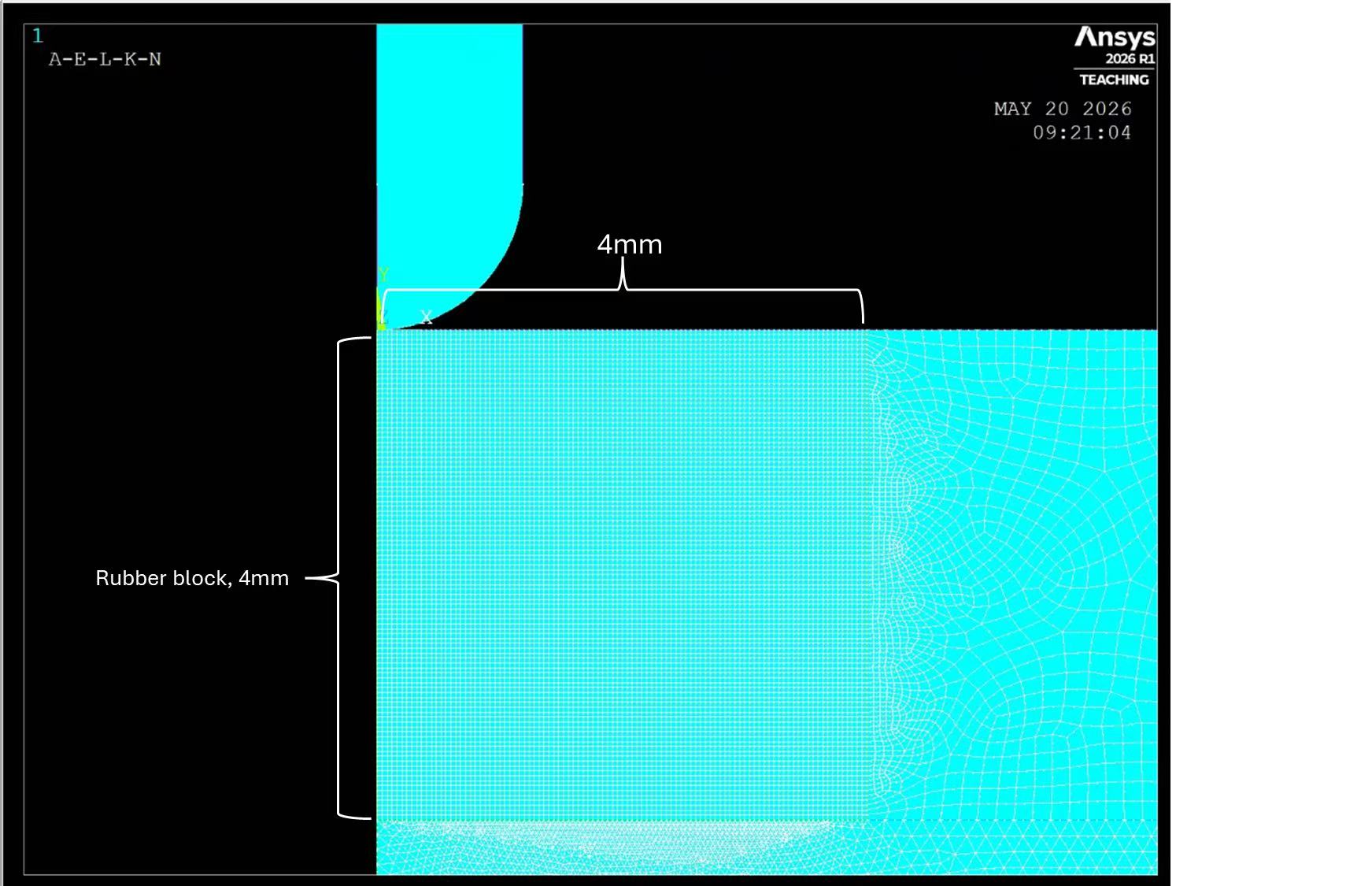
      I've been working on this 2D axisymmetric nanoindentation problem for a little while but still not able to figure out a fix. The problem is simply a half-sphere indenter drilled into the surface of a rubber block, and the goal was to indent 2.5mm into it(please see the image below). Element type: plane 182. 

      I first tried the uniform mesh, and it was able to go to 1.4mm deep(failed due to highly distorted elements and unconvergence). No matter how I modify the mesh, make it extremely fine or slightly coarse, it still fails around 1.3mm to 1.4mm range. 

      Then I tried adaptive mesh, still fails at 1.4mm, and it doesn't seem to improve much

      commands be:

      "

      ALLSEL,ALL
      ESEL,S,ENAME,,182
      CM,C1,ELEM
      ALLSEL,ALL
      NLAD,C1,ON,,,1
      NLAD,C1,ADD,MESH,SHAPE,110     
      NLMESH,NLAY,50               
      NLMESH,GRAD,1              
      NLMESH,SRAT,0.10             
      NLAD,ALL,LIST,ALL
      NLMESH,LIST
      ALLSEL,ALL

      "

      I set the corner angle to be 110 degrees because the adaptive mesh never seems to get triggered if it's a bigger angle...

      My question is how to fix the non linear adaptive mesh commands so it actually helps and indents to 2.5mm.


      Thanks!

    • peteroznewman
      Subscriber

      Please show the material constants used for the rubber.  Did you use a hyperelastic material model?  Do you have experimental hyperelastic test data for the rubber that you can share?

      Did you set any Keyopts for the rubber such as Keyop(6)=1 for the mixed u-P element formulation?

      What material is outside the 4 mm square face that is the radial slice of the rubber disk?

      How is the rubber disk connected to the outer material?  Is it Shared Topology or is there frictional contact or bonded contact? It may be easier to converge if the rubber disk was allowed to slide along the bottom and side of the “container” especially if the container sides were higher than the top surface of the rubber.

      What is the radius of the indenter tip?  What is the material for the indenter?  What contact settings were used between the intender tip and the rubber top?

      • zwang05
        Subscriber


        Thank you so much for your reply!


        1. I’ve been using a linear elastic material model. “

          MP,EX,2, modulus1

          MP,PRXY,2, poissonratio1

          ” The rubber block was set to have a 1GPa modulus and a 0.4 Poisson ratio. Unfortunately, I don’t have any data to share, and I am just hoping to get the simulation results for the load-displacement curve.
        2. For the rubber, I have the following for KEYOPT: “

          ET,1,PLANE182

          KEYOPT,1,1,0    

          KEYOPT,1,3,1    

          KEYOPT,1,6,0 “
        3. Sorry about the confusion. The material outside 4mm is still the rubber block. I split the whole block into 3 parts so the mesh gradient goes from extremely fine to coarse. 
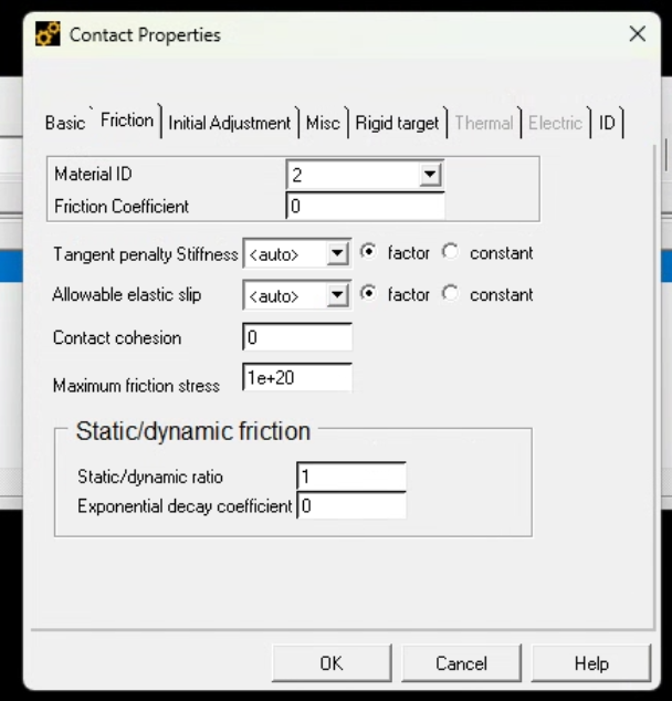
        4. All the parts have been glued together and the contact pair (indenter and rubber block) was set as frictionless. And yeah, the bottom of the rubber block was set to be able to move freely in the horizontal direction. 
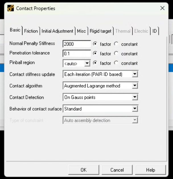
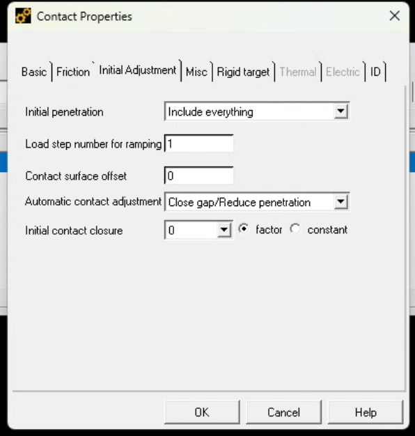
        5. The radius of the indenter was 1.19mm and it was set as rigid in contact pair. And the basic settings for contact pair are shown below, the reason why I have 2000 normal penalty stiffness is that I want to minimize penetration into the surface:


        Thanks!


    • zwang05
      Subscriber

      1

    • peteroznewman
      Subscriber

      Make a linear element mesh that is biased to the Y axis horizontally, but uniform vertically.  You want tall, skinny elements on the Y-axis as shown below.  Make the rubber disk from a single face, there is no need to split the rubber into multiple faces. There is no need for Nonlinear Adaptive Meshing. Under the rubber disk, add a base part so the rubber can lift off.
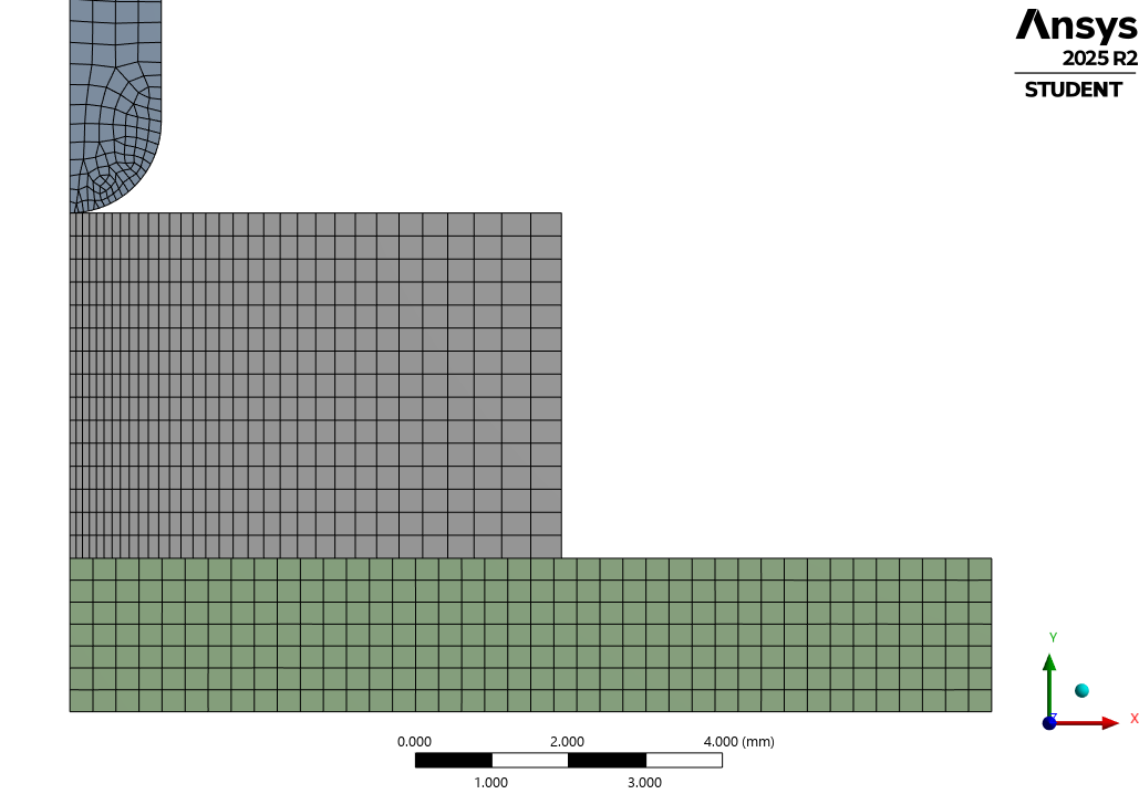
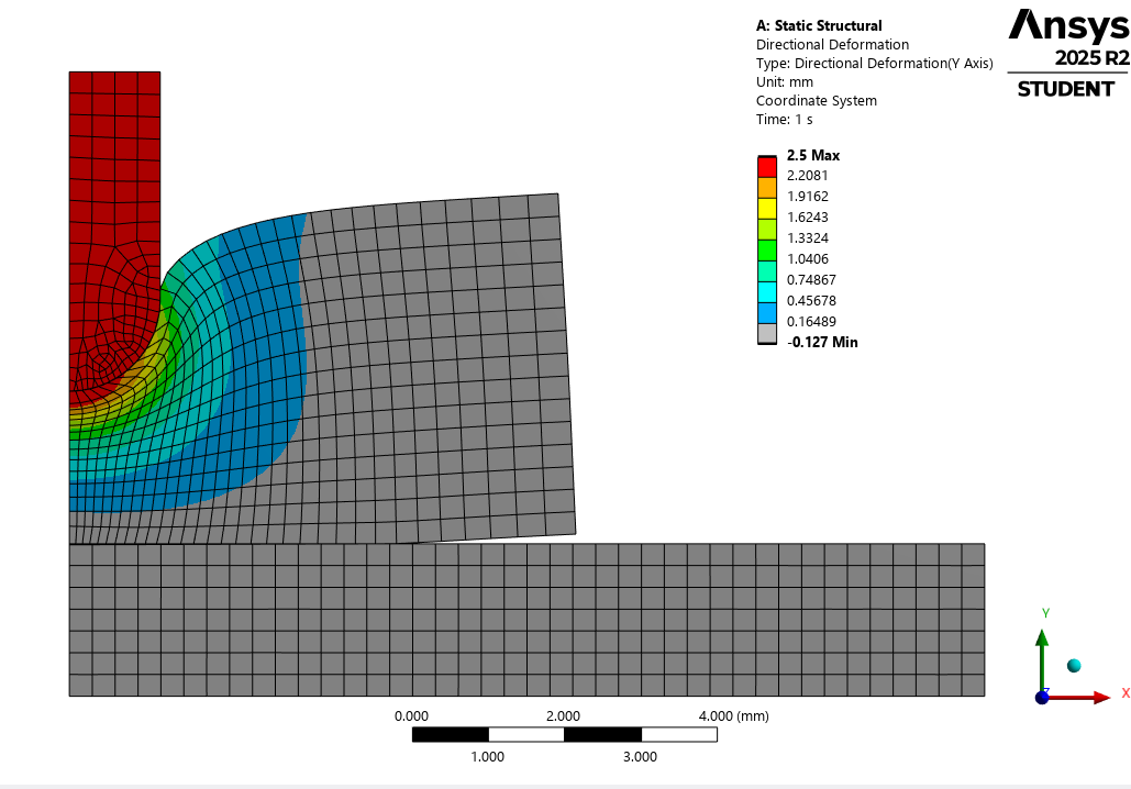
      Under Engineering Data, in the Explicit Materials category, add the material called Rubber1 that uses an Ogden Hyperelastic Material Model and assign it to the rubber disk.

      I set Frictional contact between the indenter edges and the top edge of the rubber to have a Coefficient of Friction of 0.2 and did the same between the top of the base plate and the bottom edge of the rubber.  Set Auto Time Stepping to On and use 50 Initial and Minimum Substeps, with 500 Maximum Substeps. Turn On Large Deflection.
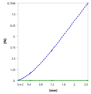
      With default settings for the contact, the Penetration is less than 0.005 mm at the indenter.
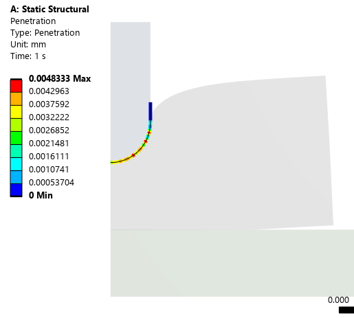
      However, the penetration is larger on the base plate.
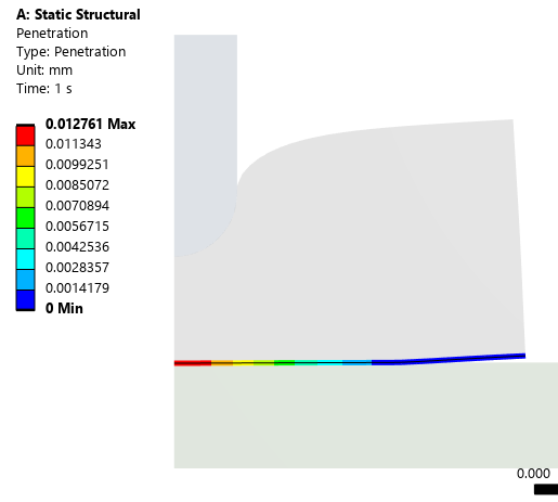
      By setting the Penetration tolerance to 0.001 mm, the new solution shows a much smaller penetration.
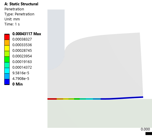
      Good luck!

      • zwang05
        Subscriber

        Thank you so much for your help!

        I am doing it right now, I will let you know whether it works!

        Once again, really appreciate your help and time!

      • zwang05
        Subscriber

        sorry one quick question, did you set a value for the normal stiffness or just program controlled?


    • peteroznewman
      Subscriber

      I used Program Controlled for Normal Stiffness, however, when I changed Penetration Tolerance, the way that was accomplished internally is by increasing the normal stiffness.

Viewing 4 reply threads
  • You must be logged in to reply to this topic.
[bingo_chatbox]