TAGGED: #Modal_Analysis, added-mass-modal-analysis
-
-
May 9, 2023 at 6:56 pm
Aina Najeeha Shaffrik
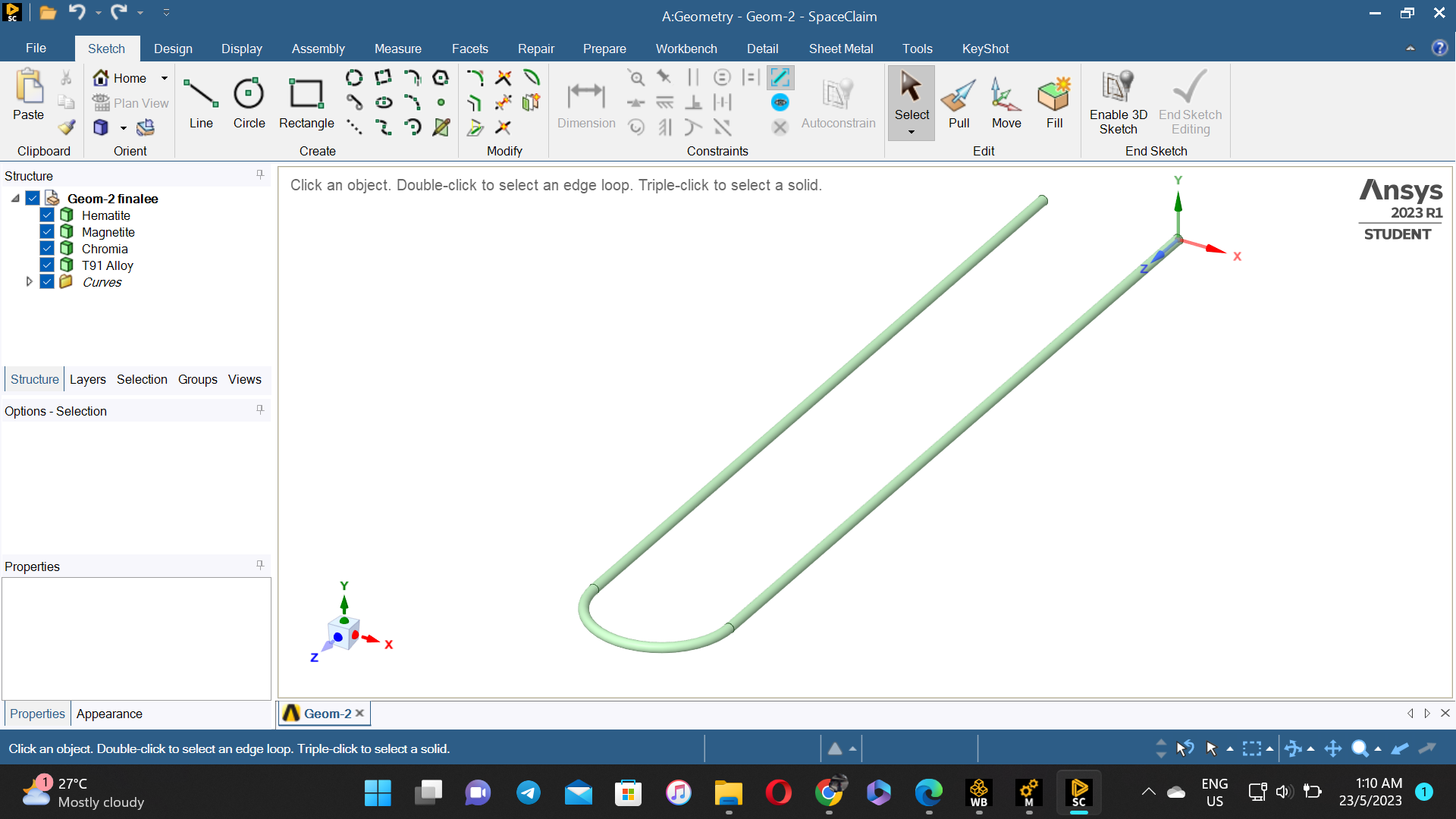
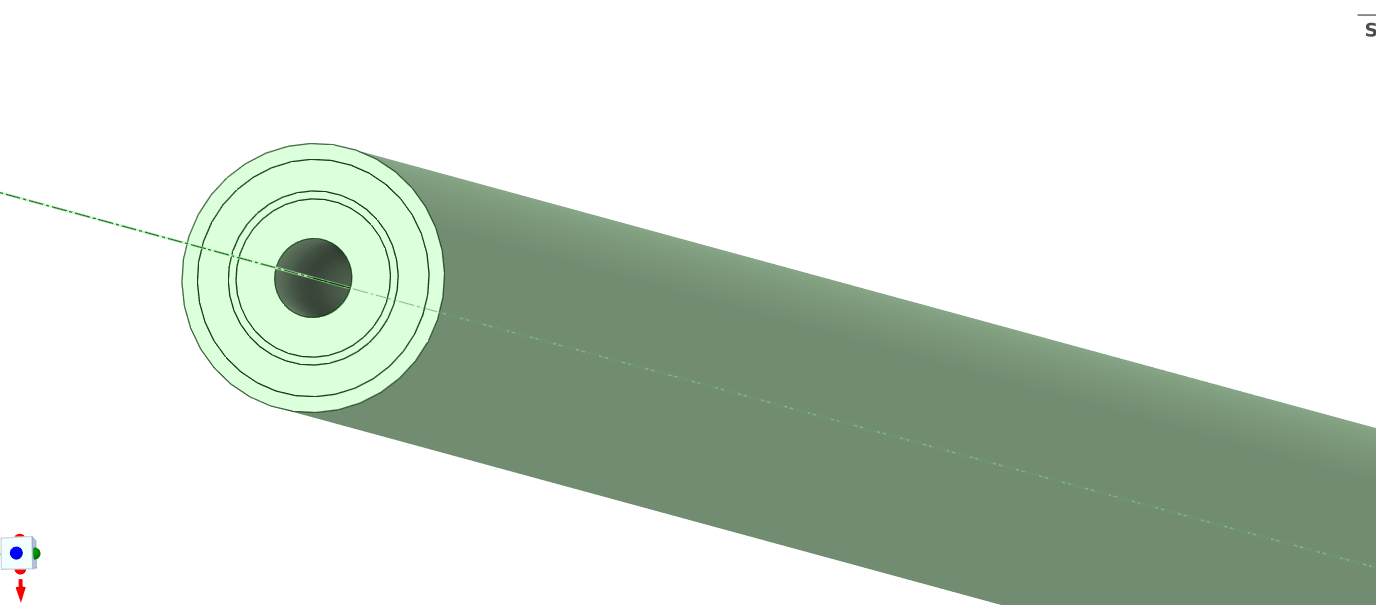
Subscriberhi all, may i know what is the easiest way for me to construct a U-tube shape with different thickness of oxide layers coating it? the oxide layers are chromite, ferrite and magnetite. im interested to perform modal analysis for each layer. for example for the first case, i would like to know the natural frequency of just the tube + 1mm of chromite. the next case is the natural frequency of the tube + 1mm chromite + 5mm magnetite. and lastly the natural frequency of these layers + 2mm of hematite. do i hv to make separate geometries just to get all these cases or 1 geometry is enough? also how to cooperate with mass bcs as the oxide layer thickens, the mass gain causing the natural frequency to change.
-
May 10, 2023 at 11:55 am
peteroznewman
SubscriberIn SpaceClaim, construct a solid body for the U-tube.
Double-click on the inside face and you should pick up all three faces. Type Ctrl-C, Ctrl-V. That will copy and paste the inside faces and create a surface. Hide the solid body. Use the Pull tool to pull the surface into a solid that is 1 mm thick. Repeat two more times to get the other layers. Unhide all the solid bodies.
On the Workbench tab, click the Share button to cause the solids to use shared topology so the mesher will connect all the solids without using contact in Mechanical.
Make a Modal analysis for all layers. Once that solves, you can duplicate the analysis and suppress layers until you get down to the U-tube.
-
May 22, 2023 at 4:24 pm
Aina Najeeha Shaffrik
Subscriberit works, thanks! is there any alternative for me to combine all cases in just one workbench? like i imagine it would be great if i could hide and unhide the layers during the intended simulation cases. is it possible? or do i have to simulate each case in a different workbench and file?
-
May 22, 2023 at 4:41 pm
peteroznewman
SubscriberIn Workbench, right click on the title bar of the first Modal analysis with all the layers and select Duplicate from the drop down menu. You can make as many duplicates as you want to separate out the layers. You can rename each Modal system to know what layers are active in each block. Then there is just one Workbench project file and folder.
-
May 22, 2023 at 5:12 pm
Aina Najeeha Shaffrik
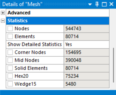
Subscriberthanks, for the feedback. i also would like to know if you could reduce the number of nodes in my file since im only using the student version. it turns out that my mesh is way too big to process in this version. how do i make it right without having to alter the geometry of my model since every layer of my tube is crucial.
here is my geometry.
-
May 22, 2023 at 5:28 pm
peteroznewman
SubscriberClick on Mesh and set the Element Order to Linear. That will reduce the number of nodes.
Insert a Mesh Method of Sweep and set the element size along the sweep direction to a larger value to use longer elements along the pipe direction. That will reduce the number of elements.
-
May 22, 2023 at 5:43 pm
-
May 22, 2023 at 8:28 pm
peteroznewman
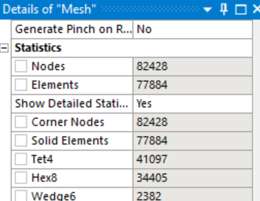
Subscriber32k was the limit many years ago. The current limit is 128k nodes or elements for Mechanical models. You are well under that limit.
-
May 23, 2023 at 12:04 pm
Aina Najeeha Shaffrik
Subscriberi managed to generate the mesh but when i run the simulation for steady state thermal, it still shows "Your product license has numerical problem size limits, you have exceeded these problem size limits and the solver cannot proceed." how to fix this?
-
May 23, 2023 at 3:38 pm
peteroznewman
SubscriberDid you use Shared Topology and did you delete all the Contacts?
The limit is based on the highest node number, not the number of nodes.
Under the Mesh branch, insert a Mesh Renumbering object and set it to compress the numbers.
-
May 23, 2023 at 4:12 pm
Aina Najeeha Shaffrik
Subscriberhow to use shared topology and delete all the contacts? sorry this is my first time using a little complex geometry. btw ive tried mesh renumbering and compress it but the problem stays the same. how?
-
May 23, 2023 at 5:56 pm
peteroznewman
SubscriberOpen your Geometry in SpaceClaim, go to the Workbench tab on the ribbon and click the Share button and click the green check mark. Close SpaceClaim.
Open your model in Mechanical. Under the Connections folder, delete all the contacts. You may need to repair the Fixed Support.
Click on Mesh and Clear Generated Data. Click on Generate Mesh. Try to solve.
-
May 30, 2023 at 10:49 pm
-
May 31, 2023 at 1:29 am
peteroznewman
SubscriberCan you provide a link to the journal article?
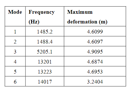
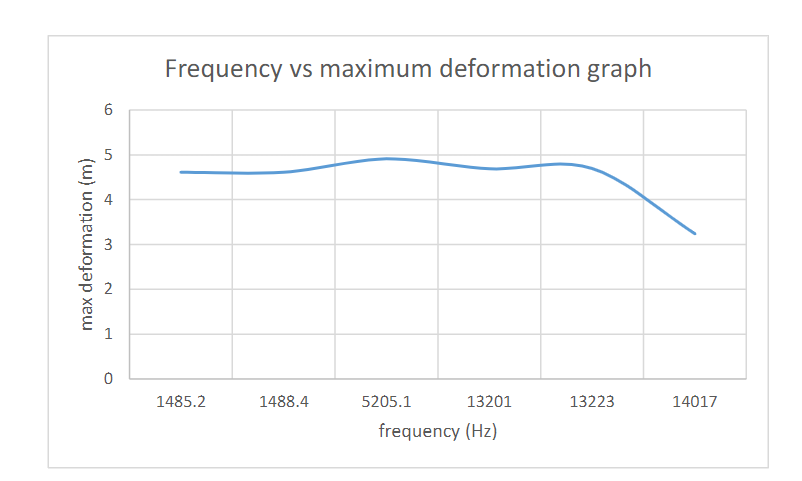
Perhaps they were doing Harmonic Response analysis. That is where deformation can be calculated vs frequency of the applied load.
It makes no sense to plot deformation vs frequency for a Modal analysis.
Please take the free classes on Modal analysis and Harmonic Response analysis to understand the difference.
/courses/index.php/courses/modal-analysis-in-ansys-mechanical/
/courses/index.php/courses/harmonic-response-analysis-in-ansys-mechanical/
-
May 31, 2023 at 1:46 am
Aina Najeeha Shaffrik
Subscriberthis is the link.
http://www.ieomsociety.org/singapore2021/papers/799.pdf
i would like to show theres a shift in frequency between the uncorroded boiler tube and the corroded one. if theres any possibility for me to extract meaningful results from modal analysis and harmonic response?
-
May 31, 2023 at 1:48 am
-
May 31, 2023 at 10:54 am
peteroznewman
SubscriberThe authors of the journal article do not understand Modal analysis and should not have included the deformation in Tables 7 and 8. Have you taken the free course on Modal analysis yet?
There are many ways you can show that corroded pipes have a frequency shift compared with uncorroded pipes. You can use Modal analysis, Harmonic Resposne analysis or Random Vibration analysis. Modal does not take any input load, which is why the deformation output magnitude should not be used the way it was in that paper. The modal deformation is only to understand the mode shape, the magnitude is arbitrary.
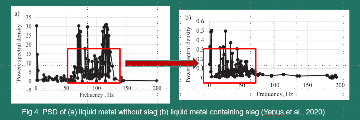
Random Vibration analysis takes a PSD input load and computes the 1 sigma deformation in the structure. You can plot the response (output) PSD of a vertex. Take the free course in Random Vibration.
-
- The topic ‘multilayered tubing with oxide layers’ is closed to new replies.


-
3377
-
1052
-
1050
-
886
-
842

© 2025 Copyright ANSYS, Inc. All rights reserved.

