MPC contact -> Element Distortion

TAGGED: contact, element-distortion, mechanical, mpc
-
-
May 5, 2021 at 9:28 am
piknockyou
SubscriberHi,
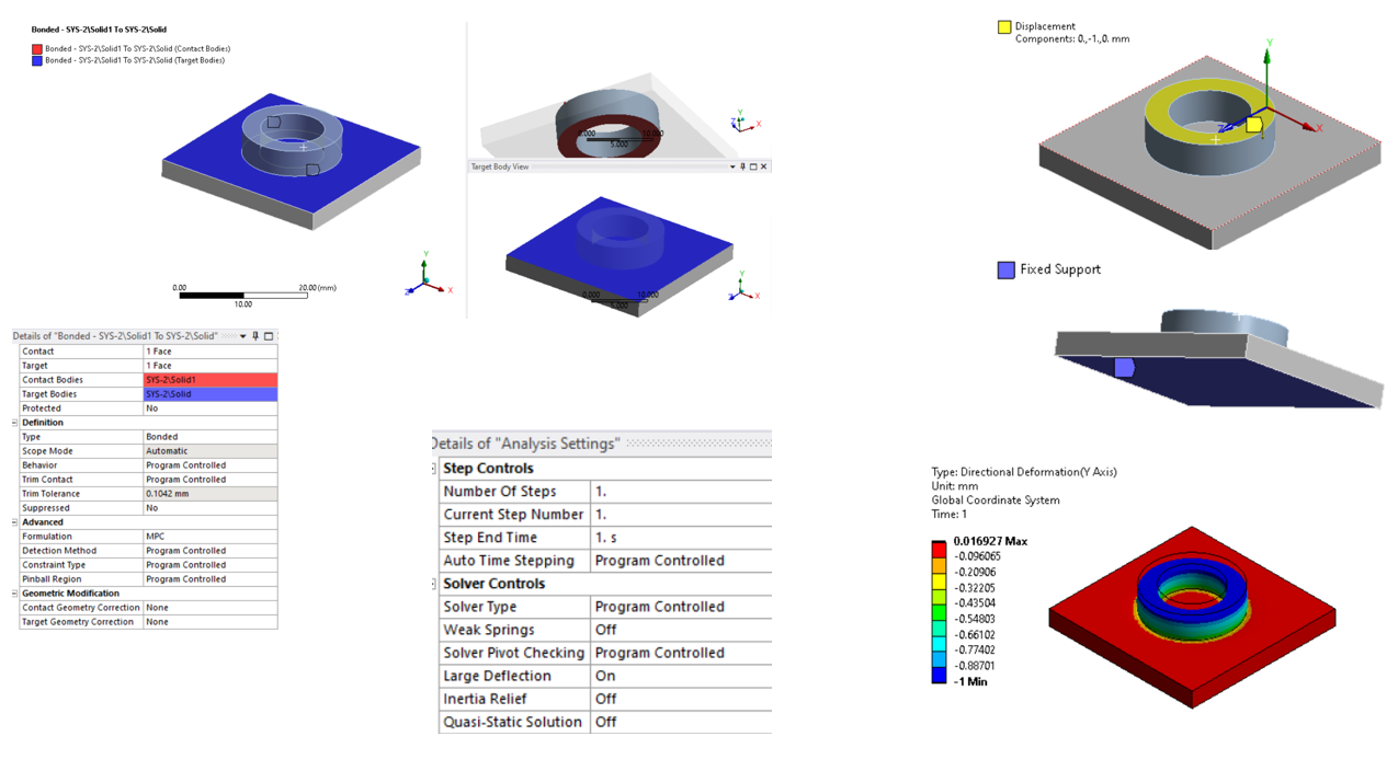
simple model:
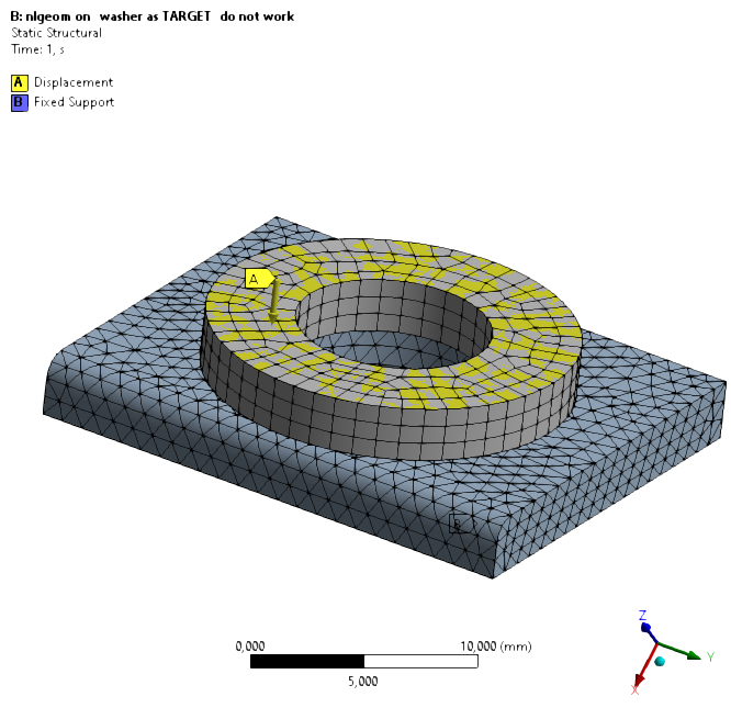
- Fixed Support: bottom surface of plate
- Displacement: 0, 1 mm
- MPC-Bonded Contact between Washer & Plate
- Large Deflection: On
May 5, 2021 at 12:49 pmAshish Khemka
Forum Moderator
Did you check the contact status before solving? Is the contact closed? If not try increasing the pinball radius only.
I have a setup similar to yours in v2021R1 and the model solves at my end without any issue:
Regards Ashish Khemka
May 5, 2021 at 5:02 pmpeteroznewman
SubscriberI notice that the Iterative (PCG) solver was used. If you set the solver to the Direct (Sparse) solver, do you get the same result?
May 5, 2021 at 5:05 pmForum Moderator
As Peter suggested - please try using a direct solver first.
Regards Ashish Khemka
May 5, 2021 at 6:22 pmSubscriber:
Thanks a lot for your work, but you can not reproduce my case with a different mesh (by the way: contact/target are flipped at your end). As already mentioned: I presented you a very simple model, but lately (2021 R1) I've been getting this element distortions more and more often between MPC-bonded contacts of different geometries - be it small, simple or very large models. It is random.
:
I get the same result for both solvers.
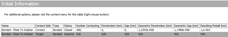
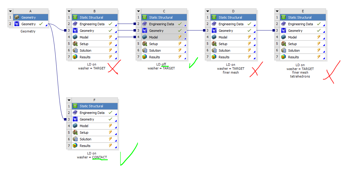
For further investigation I solved several models with different Pinball Radii.
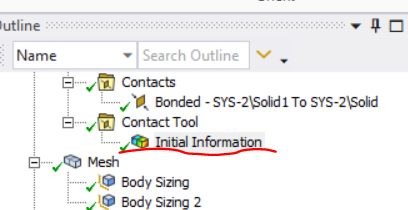
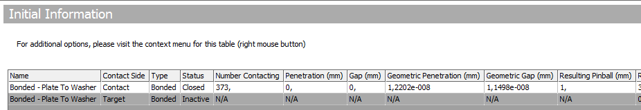
Figure 1: Initial Information from the Contact Tool
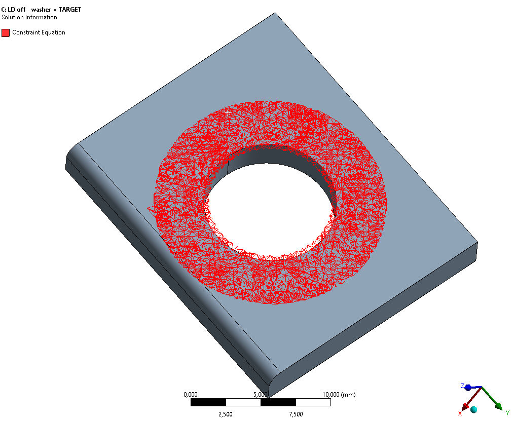
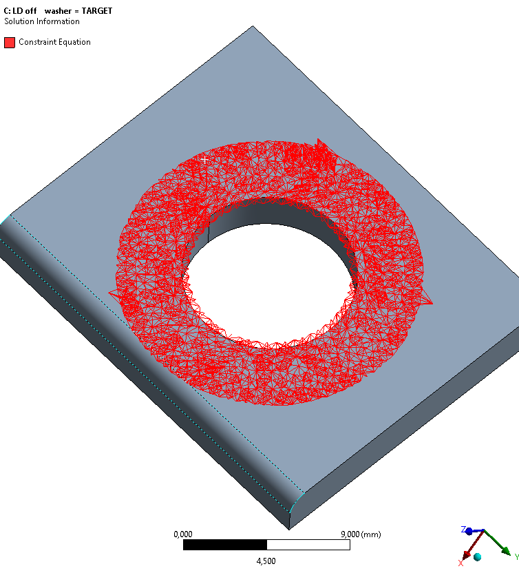
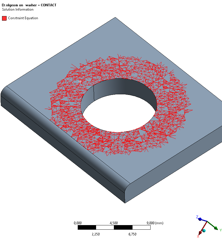
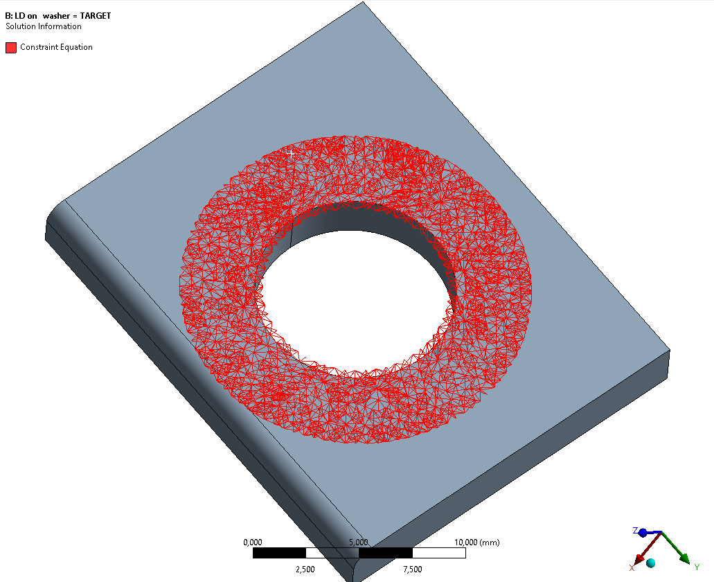
Figure 2: Constraint Equations (for illustration purposes) after successful solution with Large Deflection: Off.
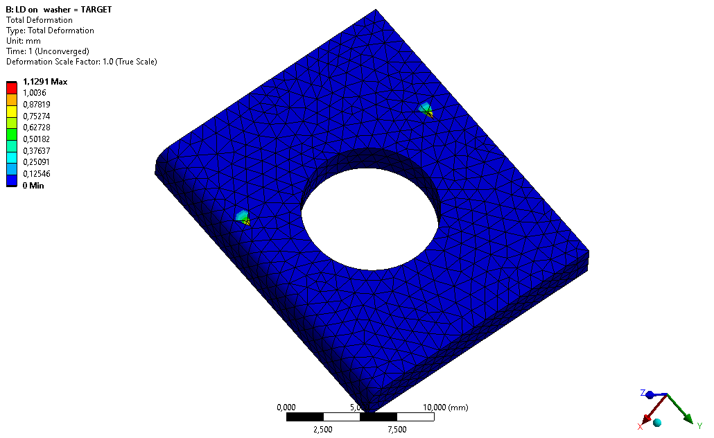
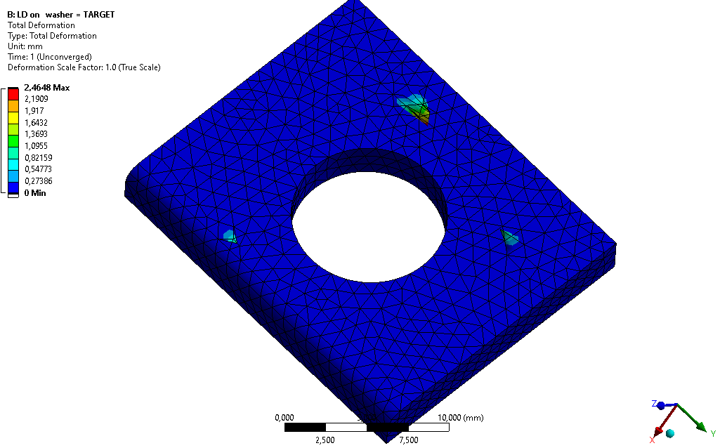
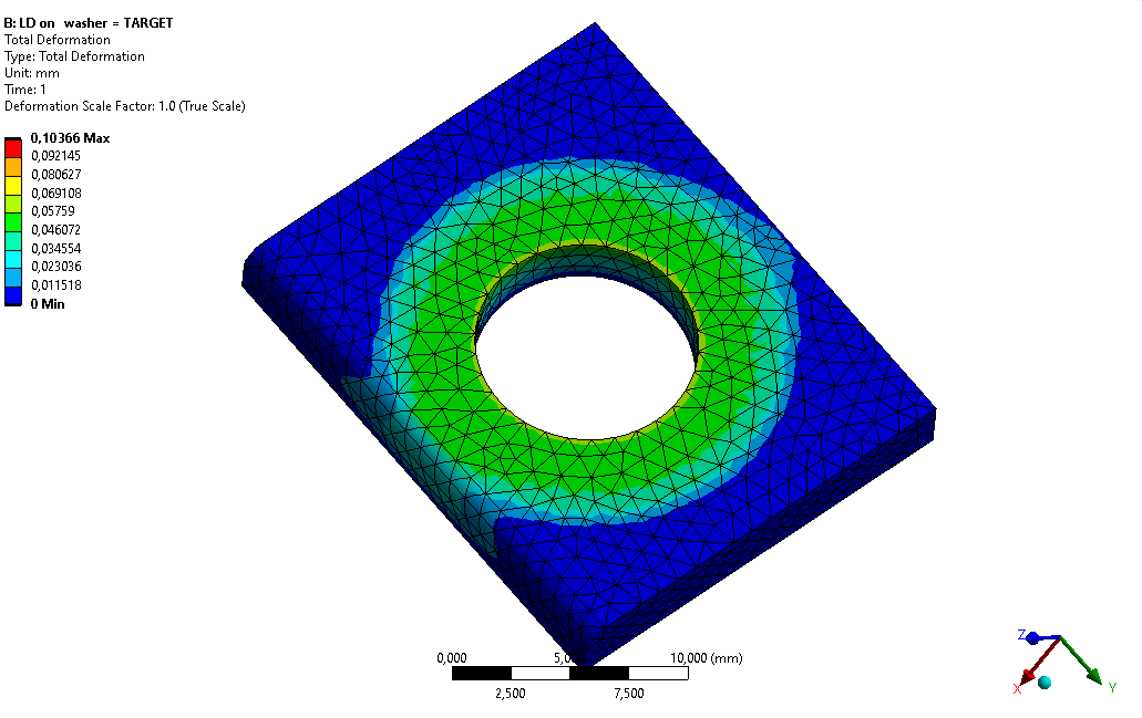
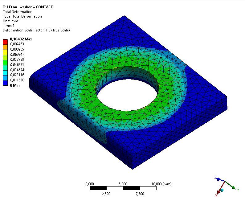
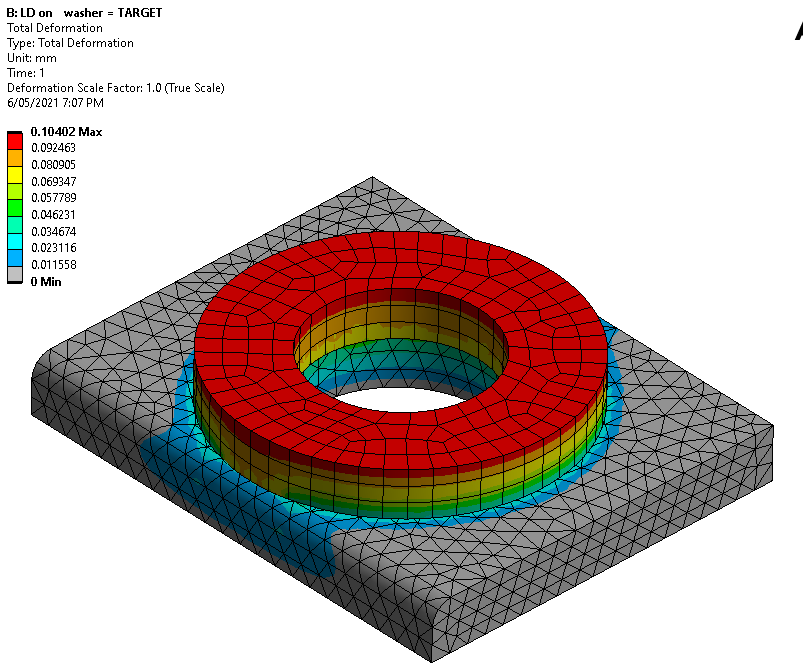
Figure 3: Total Deformation with Large Deflection: On.
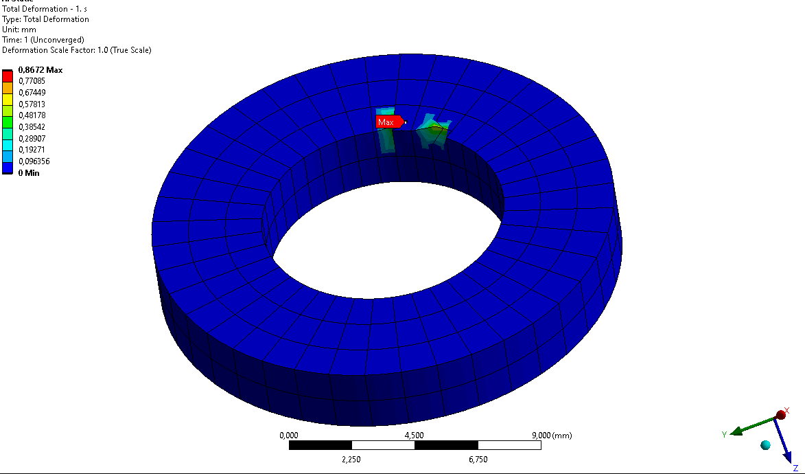
Case 1: Pinball-Radius: 0,18888 mm - Unsuccessfull!
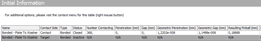
 Case 2: Pinball-Radius: 1 mm - Unsuccessfull!
Case 3: Pinball-Radius: 0,001 mm - Successfull!

Case 1 & 2: You can clearly see that some constraints are built behind the Washer Diameter. Those are the spots where the element distortions occur.
Case 3: If I set the Pinball Radius very small, no constraint are built behind the Washer Diameter and the solution is successful.
Case 4: Another way to avoid constraints behind the Washer Diameter is by switching from "Nodal-Normal to Target" to "Nodal-Normal from Contact" . This will produce the exact same results as pictured in Case 3.
All Cases will successfully solve when Large Deflection is Off.
I can not comprehend why constraints behind the touching regions should be of any problem. Especially when I flip Contact/Target side, the constraint equations become even "wilder" regarding their spread ...
 ... but it solves flawlessly:
 But this is not always the case! Sometimes the other side gets distorted! This was just an illustration, not an acceptable workaround for me.
Is this a bug?
Please help me to resolve & understand this issue.
This happens randomly & is not very uncommon anymore.
Did this never occur to you?
Thank you!
May 6, 2021 at 6:03 amBenjaminStarling
SubscriberI have not seen an increase in this occuring with releases, but have seen it before. I do not understand this comment.
Penalty Method (not applicable, b/c gaps available in some cases)
Why exactly is the penalty method not applicable? If there is a gap this can be accomodated for with contact geometry correction. One of the issues to look out for with bonded contact using penalty methods is spurious rotational energy in the model; is this what you are referring to?.
Other than pinball readius, my first impression is that the mesh is too coarse, this thinking is similar to what you have already discovered, a finer mesh will help keep the constraints closer to the contact region.
May 6, 2021 at 6:48 amSubscriberYes, I think "spurious rotational energy" is what I am referring to.
As I mentioned, there are plenty of workarounds, but I want to understand this issue.
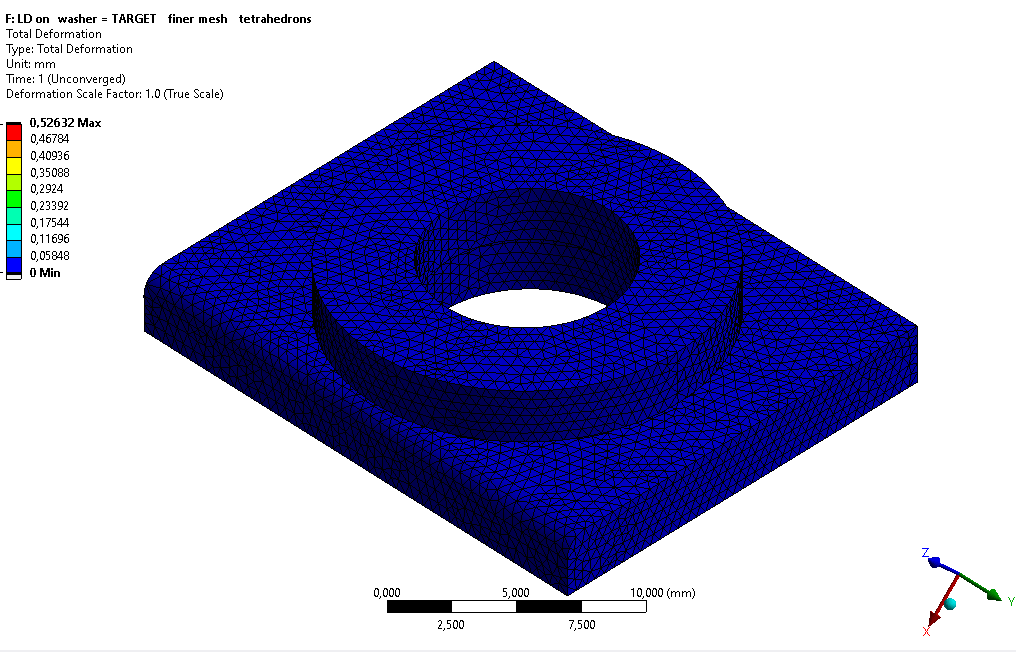
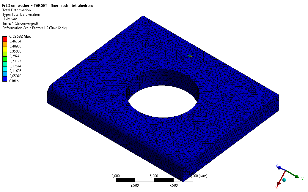
I do not share the opinion, that the mesh is too coarse at this location. In relation to the geometry dimensions I believe the model has a pretty good mesh resolution, especially because I am not trying to evaluate stresses. But anyway, here you go:
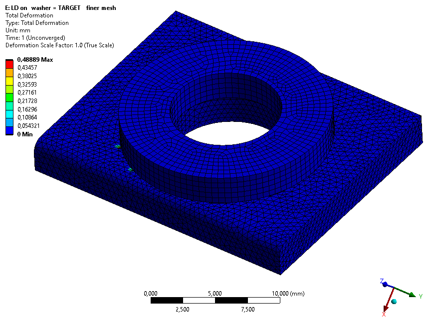 This seems to be not a mesh related issue (tetrahedrons for Washer):
I am solely here to understand what & why this is happening.
May 6, 2021 at 7:34 amSubscriberYou are not interested in stresses but contact requires a pretty fine mesh anyway, but the size it self was not my concern, rather just where the spiders end up. I built a test model with different mesh sizes, linear vs. quadratic mesh, different contact settings, changed substeps, and was not able to acheive what you are seeing. Your test case is simple enough that I am surprised that it is occuring so regularly.
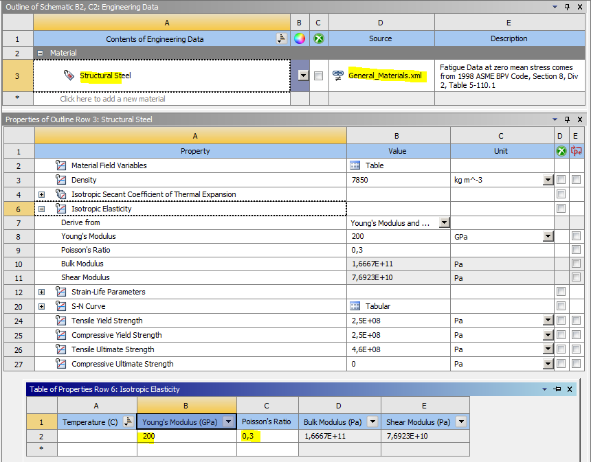
Are you using structural steel in these analysis? any nonlinear materials?
This is an odd guess, but we have had issues that have been fixed by replacing/cleaning up geometry, so considering you are not using spaceclaim, have you tried running Virtual Topology over your geometry, creating a virtual entity in as many places possible that may make sense?
Maybe time to reinstall windows
May 6, 2021 at 8:05 amSubscriber. Thank you for your effort, but as I already told,who also went through this effort, I am sure you guys are not able to reproduce my results with a different model. This is a random occurrence with MPC-bonded contacts with Large Deflection: On. I have other larger models, where I encountered the exact same problem for different geometries. And you also mentioned you have seen this before, but probably did not investigate any further.
I am using linear Structural Seel :
 My geometry is very simple & clean. Anyway, the mesh discretization is crucial and I do not see any issues with it. Only 1 Virtual Topology can be generated & does not help. And even if it helped in any way, this could have been another workaround that I am grateful about, but not really looking for. I'd like to understand what & why this is happening.
I do not need to reinstall Windows, because as already mentioned: I am a commercial user and my support was not able to explain the reason to me at this point. They had my model and were able to reproduce the same problem on a complete other machine.
May 6, 2021 at 8:16 amSubscriberAre you able to attach a copy of your project here? If others cannot replicate the issue by building a similar model, then there is something specific about your workflow that is causing this.
May 6, 2021 at 8:44 amSubscriberIt is a random occurrence. That's why it makes totally sense to me at least, that other similar models won't necessarily replicate the same issue.
Of course, if this would happen for every other MPC-bonded contact with Large Deflection: On (especially of this model simplicity), their would be an outcry, don't you think? ; )
But then (hypothetically speaking), reasons for this issue would be soon well-known, communicated and every one could live with it by using one of the plenty workarounds mentioned officially. For example a rule like: "Each face of a MPC contact pair MUST STRICTLY have the exact same outer dimensions by using imprints."
Here you go:
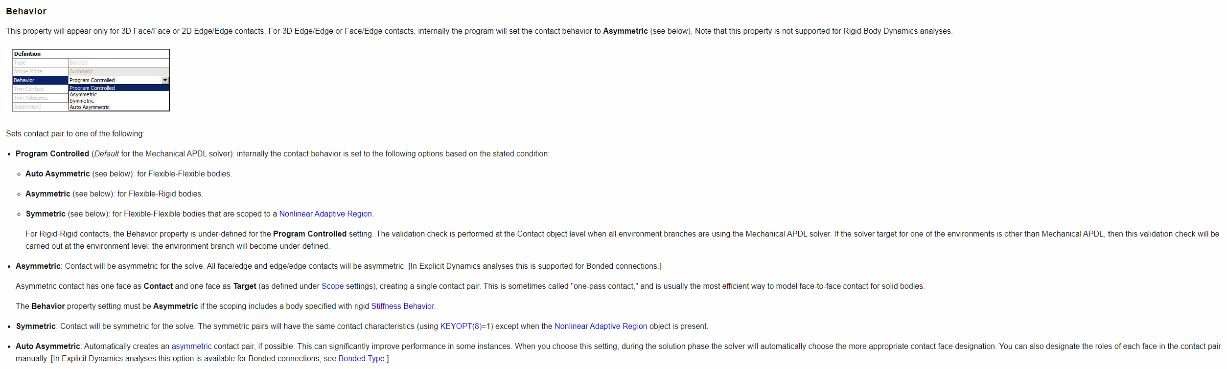
May 6, 2021 at 9:35 amSubscriberJust changing the behaviour from Asymmetric to Program Controlled got the B5 solution to converge with no issues. The program controlled option defaults to Auto Assymetric for flexible body - to - flexible body contact; Do you always set behaviour to Assymetric? I would recommend using Program Controlled for most things. The only time I change this setting is to specify symmetric behaviour for complex non linear contacts such as self contact.
I then changed this in all your models, B->F, and they all converged.
The root cause is that your washer has a small overhang over the plate hole. When this feature is present, the Auto assymetric was flipping which contact/target was active to the opposite of Assymetric, i.e. when this overhang exists, it matters which side is active in the analysis. This is why when you specify Washer=contact in the F system, the solve is successful (Assymetric always leaves the contact active, and the target inactive). I tested this by just moving the radius to be coincident, when this is the case, either side can be active in the analysis (this is what I had in my test model).
In short, MPC contact does a weird thing when a larger donut is set as the active contact, to a smaller donut as target. Why? no idea.
Also your model has multiple splines in it, which should be planar faces.
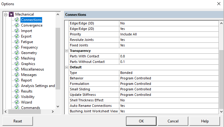
There is an option for the default behaviour in file->options
May 6, 2021 at 10:55 amSubscriber@benjaminalden´╗┐, I appreciate your time & effort. Thank you!
But all of the working and not working measures to solve this issue are well-known to me.
I mentioned in my starting post as the very first workaround out of several:
"Flip contact/target (not applicable, b/c the other side gets distorted in some cases)"
What you did, is exactly the same: When looking at the Contact Tool - Initial Information (with your setting) the Washer will automatically be assigned as contact. I am aware of this.
This was already accomplished in System F before I even started the thread and I even pictured the results in the last 2 images of my yesterday's last post (5th May) (please pay attention to the constraint equations, which spread even further).
I know you already know all that, since you mentioned System F.
But please also pay attention, what I wrote inside the parenthesis: "not applicable, b/c the other side gets distorted in some cases"
By that, I am referring to models with 12 of these Washers on a plate:
If all Washers = Target --> some regions of the plate become distorted
If all Washers = Contact --> some of their elements become distorted
 Under these circumstances, flipping contact/target is one of the worst workarounds.
I'd also like to manually decide, which side is contact/surface, because of reasons that need further explanation I'd like to avoid for now.
I'd like to mention that this problem is not limited to these geometries (washers, overhangs etc.). We are just looking at a very simple example for illustration purposes.
Anyway, as mentioned I am not looking for any well-know workarounds, which are even partially non-applicable & not helpful.
I am looking for thereason of the element distortions when modelling MPC bonded contacts with Large Deflection: On.
May 6, 2021 at 8:58 pmSubscriberYou either did not read my response fully or did not understand it.
"I mentioned in my starting post as the very first workaround out of several:
"Flip contact/target (not applicable, b/c the other side gets distorted in some cases)"
What you did, is exactly the same:"
This is not true.
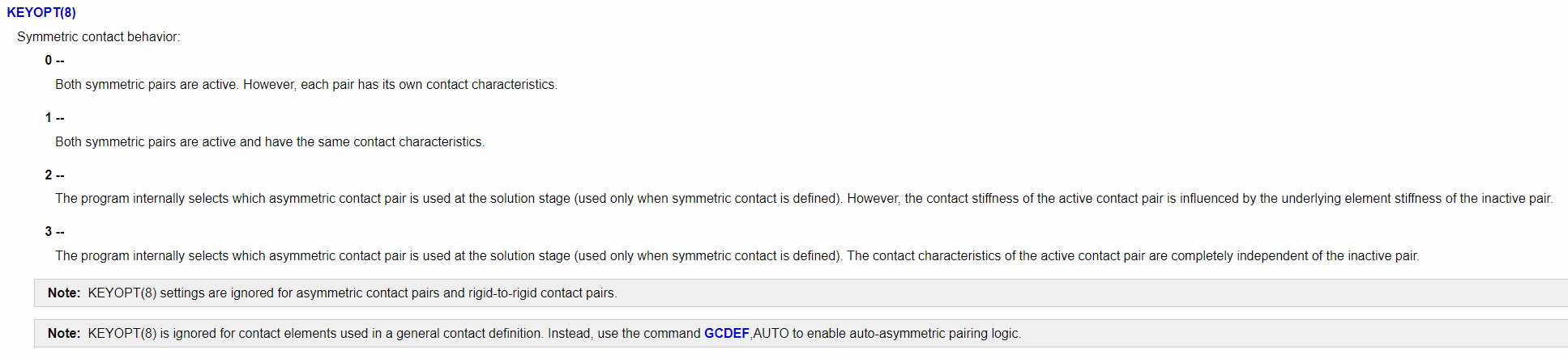
When looking at a single side of a contact pair, that side can be one of the four following options, "contact and active", "contact and inactive", "target and active", "target and inactive". The behaviour setting is not the same as flipping the contact and taget side, it is determining whether it is active or inactive. I am not going to pretend to understand the nuances of these differences, but they are different nonetheless. When behaviour is set to Auto-Assymetric, keyopt 8 on Conta174 is set to 2, when behaviour is set to Assymetric, keyopt 8 is not issued in the ds.dat. Also in the ds.dat, when behaiour is auto-assymetric, there are additional rmod commands which input real constants on the tid (target side) (these are completely missing when behaviour is Assymetric), this appears consistent with keyopt 8 = 2, as this states that both sides of the contact pair will be used to determine the stiffness of the contact.
 i.e. when behaviour -> program controlled, it does not matter which side is contact and which side is target, the solver is selecting the best options for you.
You did not answer the question Why are you using behaviour -> assymetric?
As per the Ansys help, this option is inteded for use with rigid body - flexible body contact. The shortest answer I can offer currently is that you are using the wrong setting, and should be using program controlled. This isn't a "Workaround" it is just how the application works; it is the default option and it is the best option for most scenarios.
 That being said it doesn't appear you are interested in this. If I am interpretting you correctly, you may be after one or both of the answers to the following.
What is the logic in APDL that causes it to create a seemingly incorrect internal constraint equation such that we get this result?
What is the actual internal constraint equation, that is going into the matrices, which are creating what appears to be singularities?
My stab in the dark is that it is not correctly accounting for the stiffness of both sides of the contact pair (as per keyopt 8). This may be a bug or intentional/predictable behaviour. Unfortunately I cannot answer further than this, and I do not think you will get more of an answer in this forum. The developers are not super active here, of which, you would need to find one that specifically works with contact to get a full answer.
To answer your question as directly as I can.
What is the reason of the element distortionswhen modellingMPC bonded contactswithLarge Deflection: On.
When the contact behaviour is set to Assymetric, the contact pair is implemented without keyopt 2, which results in the contact stiffness being determined/influenced by only the contact side of the contact pair. This can (but not always (seemingly randomly)) lead to incorrect internal constraint equations. This is not an issue with large deflections off, as the stiffness and geometric properties of the model are not updated during the solution. In general, linear solutions can always run when there is a singularity present, where as non linear models will have some trouble converging or fail to converge at all, due to the singularity.
July 16, 2021 at 10:15 amSubscriberHello ´╗┐@BenjaminStarling´╗┐ I'd like to address your points.
1. Yes, you are correct. I should not have simplified by saying the contact behaviour "Auto-Asymmetric" is the same as flipping an "Asymmetric" contact to the same configuration regarding the activity status. I was actually aware of the different assignments of the Keyopts by selecting the one behaviour or the other. But in my use-cases, selecting the same configuration for either ÔÇ£Auto-AsymmetricÔÇØ or ÔÇ£AsymmetricÔÇØ contact the results are always nearly identical. There might be microscopic difference regarding the stresses/deformations, thus neglectable. ThatÔÇÖs why I said that they are exactly the same. But they are not.
2.I will in most cases NOT leave the contact behaviour to "Program Controlled" = "Auto-Asymmetric". I always prefer setting "Asymmetric" when working with MPC bonded contacts. The reason behind this is, by doing this, in most cases I can control how far the MPC constraints are spread on the contact faces and avoid overconstraints at neighbouring contacts. If you do not exactly know what I mean by that, just establish contact between two plane bodies. One needs to overlap the other. Solve twice for flipped contact/target. YouÔÇÖll notice that most of the time, if the larger face is set to contact, MPC constraints are built only within the surface of the smaller face , thus no overconstraining of neighbouring contacts. Here is a comparison: Larger Face = Contact VS Smaller Face = Contact
 3. Thanks a lot for your effort & ideas why this might be occurring. I wish the developers could clear it up.
I am thankful for any other ideas.
July 16, 2021 at 11:19 amSubscriberAddition to my point 1: Anyway, this does not change the fact, that by selecting "Auto-Asymmetric", the same configuration is established (washer = contact) which worked right from the beginning anyway, which is similar to the workaround flipping contact/target for an asymmetric contact ...
August 4, 2021 at 8:18 amSubscriberThis is kind of my point though, with program controlled, I have never had it choose the wrong face/cause such NL convergence issues as you have posted above. Do you have a model or example where this has occured? If the option did not say "Assymetric", but instead "Rigid to Flexible" I would imagine you would never have started using it.
I originally stated that your mesh looked a bit coarse. If you care about results around your bolts/washers, then the mesh you are showing is a bit coarse, if you are not worried then it is fine, but then you should also not be worried about overlapping contacts in these areas. But obviously imprinting faces/refining mesh in the area is another way to control the spiders/prevent over constraint of neighbouring faces; in all instances MPC contact will only produce a constraint to a node that is attached to an element face that forms the contact pair.
Viewing 16 reply threads- The topic ‘MPC contact -> Element Distortion’ is closed to new replies.
Innovation Space Trending discussions
 Top Contributors
-
peteroznewman
 5849
5849 -
scabo
 1906
1906 -
Dennis Chen
 1420
1420 -
javat33489
 1305
1305 -
Shyam Prasad V Atri
1021
Top Rated Tags
© 2026 Copyright ANSYS, Inc. All rights reserved.
Ansys does not support the usage of unauthorized Ansys software. Please visit www.ansys.com to obtain an official distribution.
-


The Ansys Learning Forum is a public forum. You are prohibited from providing (i) information that is confidential to You, your employer, or any third party, (ii) Personal Data or individually identifiable health information, (iii) any information that is U.S. Government Classified, Controlled Unclassified Information, International Traffic in Arms Regulators (ITAR) or Export Administration Regulators (EAR) controlled or otherwise have been determined by the United States Government or by a foreign government to require protection against unauthorized disclosure for reasons of national security, or (iv) topics or information restricted by the People's Republic of China data protection and privacy laws.
