-
-
June 14, 2026 at 12:38 pm
-
June 14, 2026 at 1:31 pm
peteroznewman
SubscriberThe Move tool can move a surface body.
The Facet body is not useful for meshing, you should convert that to geometry.
-
June 14, 2026 at 6:26 pm
Hasan
SubscriberHave sketched this surface, tried to user Split tool to cut a print on the flat surface and then subtract the outer edges of the created rectangle, just to create a cover. Didn't work, how to print the tube edges on the created square?
Drew a circle and tried to use blend to link circle edge with tube opening edges but did'nt work.
-
June 14, 2026 at 9:20 pm
-
June 15, 2026 at 8:27 am
-
June 15, 2026 at 9:45 am
-
June 15, 2026 at 10:00 am
-
June 15, 2026 at 12:56 pm
-
June 15, 2026 at 1:14 pm
-
June 15, 2026 at 3:27 pm
-
June 15, 2026 at 3:47 pm
-
June 15, 2026 at 4:52 pm
peteroznewman
Subscriber
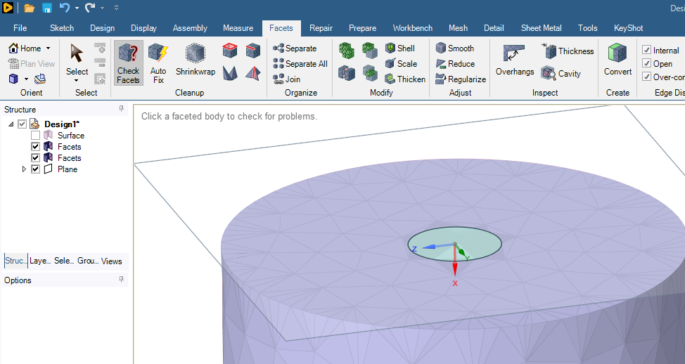
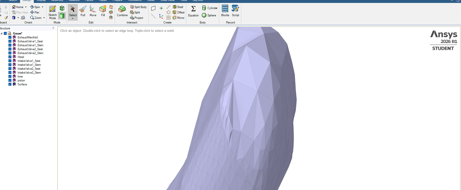
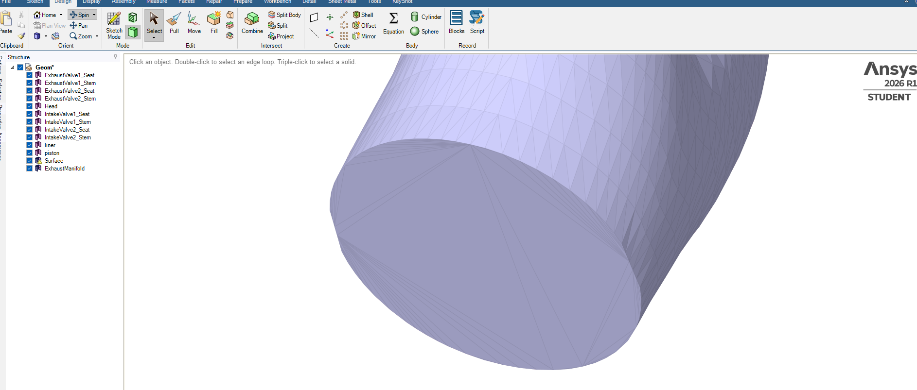
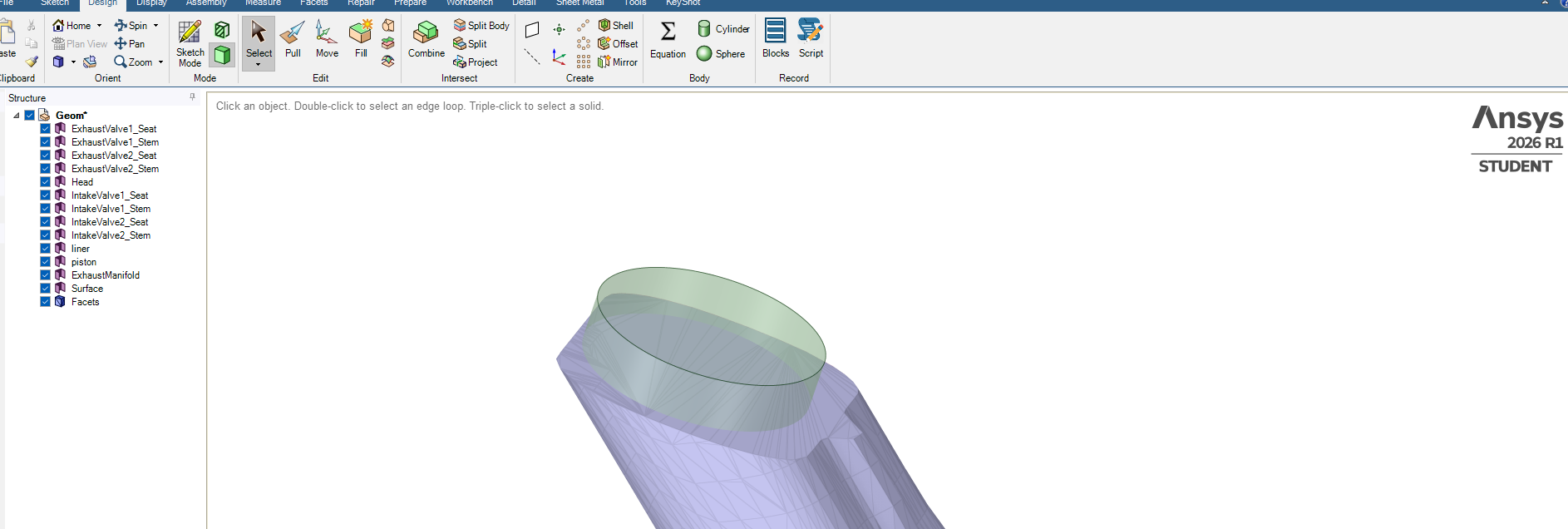
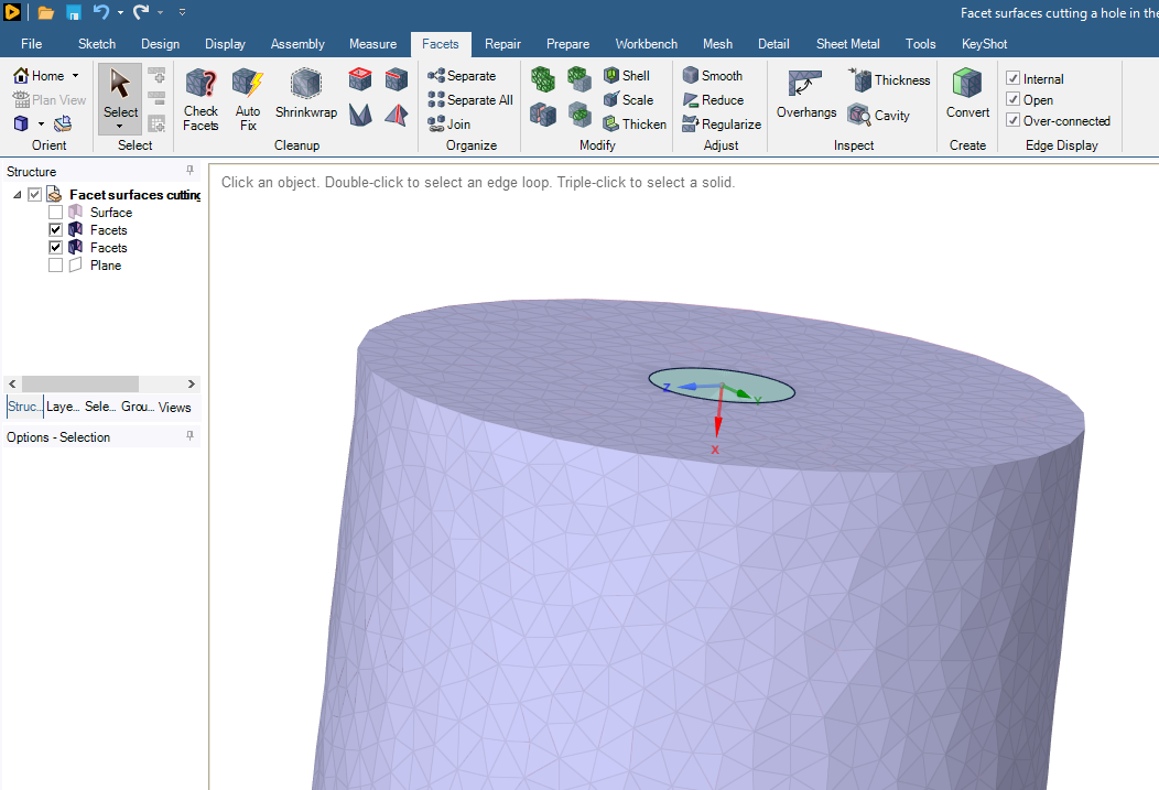
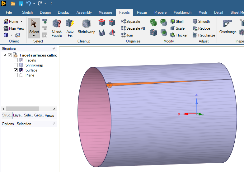
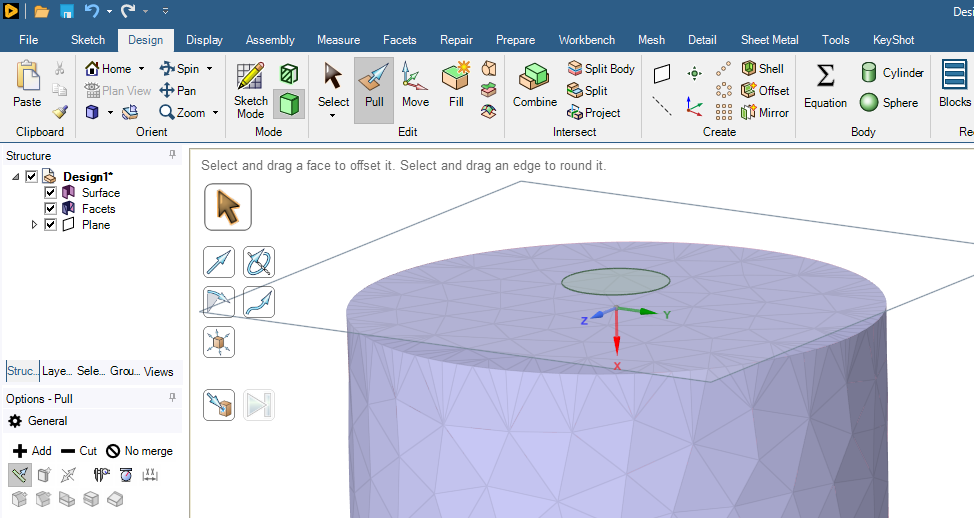
You have a plane that is near the open end of the Facet surface. It will be best if you move the plane a small distance above the end cap.
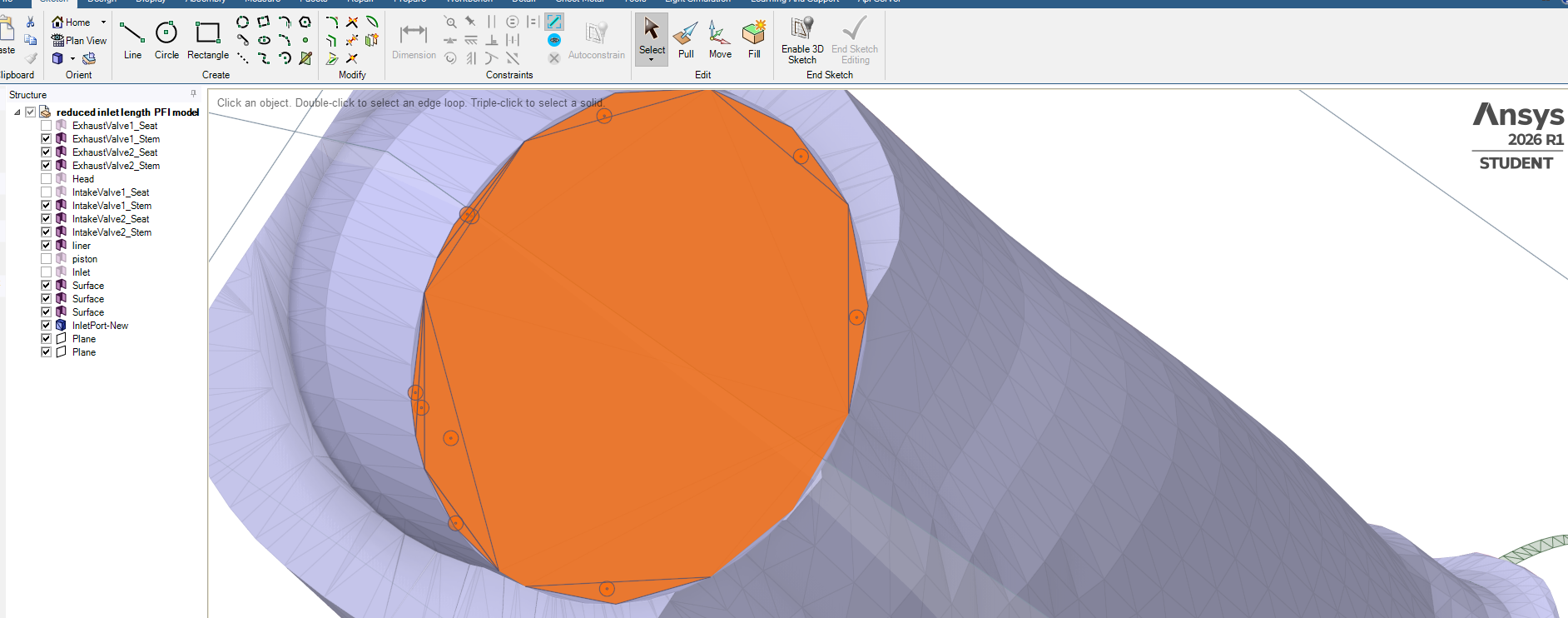
On the Design tab with the Select tool, select that plane then click the Sketch Mode button. Pick the Circle tool to sketch on that plane, then End Sketch Editing. You will get a circular geometry face.
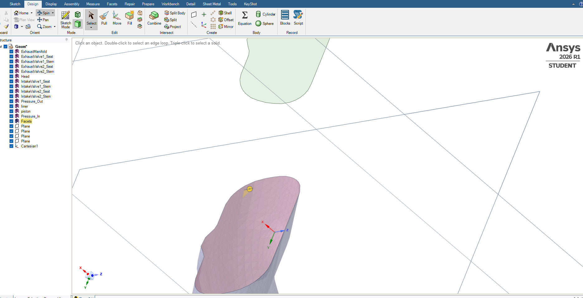
Use the Pull Tool to create a cylindrical solid that passes a small distance through the end cap facet body surface.
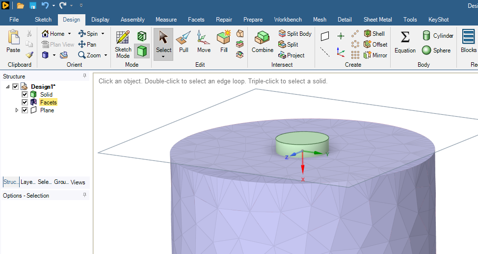
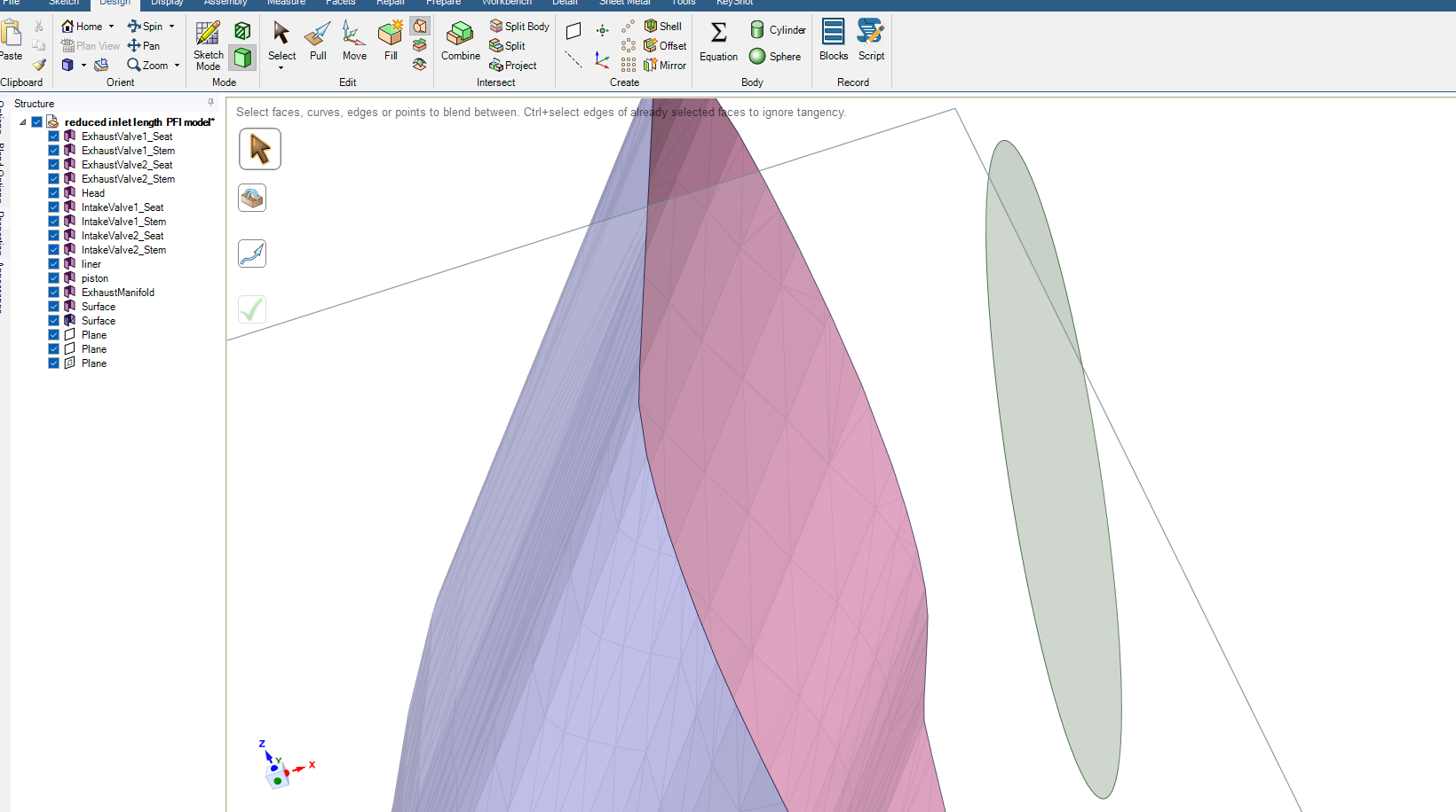
Select the cylindrical face of the solid and type Ctrl-C, Ctrl-V to get a surface, then delete the solid body.
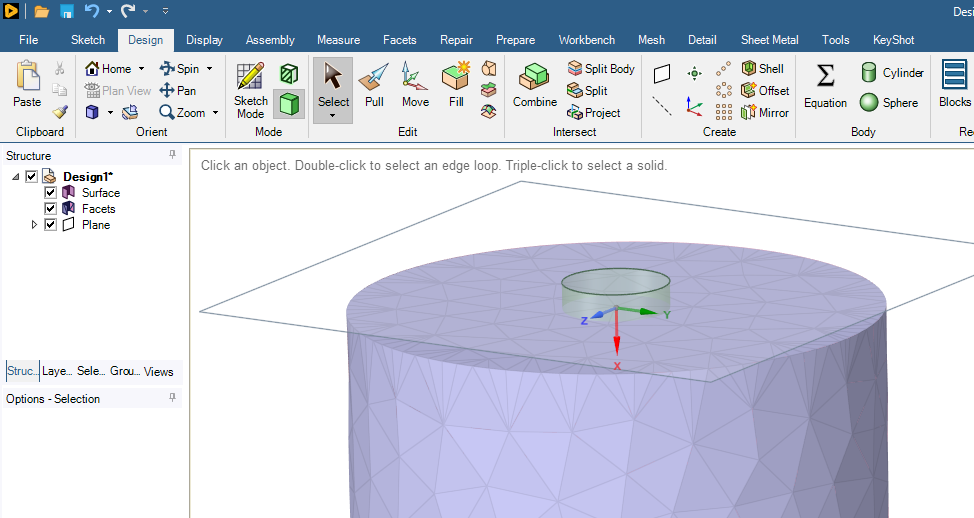
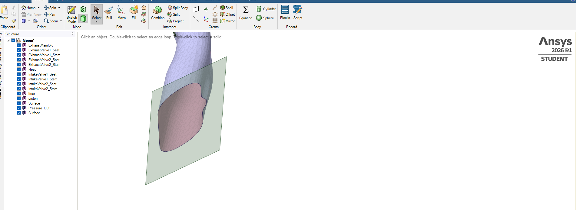
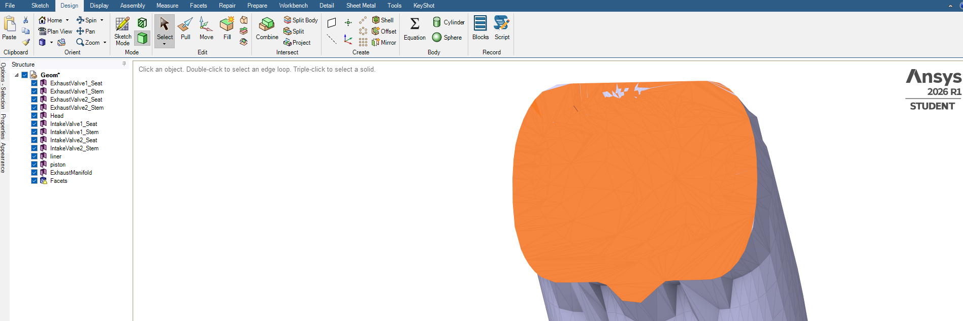
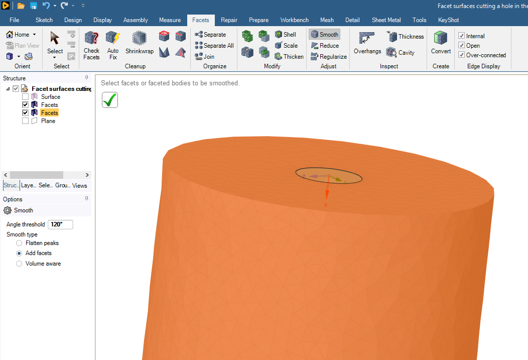
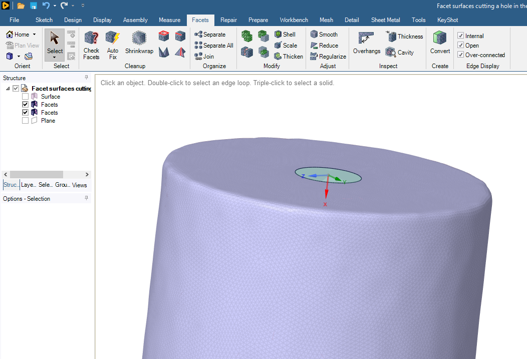
On the Facets tab, use the Split button.
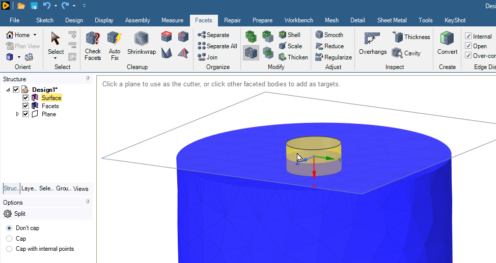
Now you have two Facets bodies, the large body with a hole and a small body that fills the hole.
-
June 16, 2026 at 8:17 am
Hasan
Subscriber-
June 16, 2026 at 2:28 pm
peteroznewman
SubscriberThe workflow I described above only works on a surface facet body. You are trying to apply it to a solid facet body.
-
-
June 16, 2026 at 10:17 am
-
June 16, 2026 at 11:30 am
-
June 16, 2026 at 12:08 pm
Rob
Forum ModeratorIs this for a CFD model?
-
June 16, 2026 at 1:05 pm
peteroznewman
SubscriberRepair the facet surface using the Check Facets and the Auto Fix buttons until the check comes back with no defects (except not watertight).
Here is one of my videos:
If you can share your archive, I can take a look at it. In Workbench, use File, Archive to create a .wbpz file. Upload that file to a file sharing site such as Google Drive. Set Sharing so that Anyone with the link can download, don't leave it with the default Restricted setting.
-
June 17, 2026 at 11:21 am
Hasan
Subscriber-
June 17, 2026 at 3:04 pm
peteroznewman
SubscriberThe facet body named InletPort-New is a Solid body, not a Surface body so maybe you don’t have the cover you want. I think at the end of the day, you want a watertight solid facet body for the entire manifold with named selections for inlets and outlets that consist of facets on the solid body.
-
-
June 17, 2026 at 11:39 am
Hasan
SubscriberSelected all elements maually and went to Groups, then selected "Create NS" to give it an ioening name.
Thanks for your help, peteroznewman you are good in Spaceclaim.👍
-
June 17, 2026 at 12:34 pm
-
June 17, 2026 at 3:01 pm
peteroznewman
SubscriberDo you mean sharp edge of the outline of geometry or do you mean sharp angles at the vertices of individual facets?
Here are sharp edges in the geometry.
Use the Smooth button with an Angle Threshold > 90 degrees.
Here is the result.
If you have sharp vertices on individual facets, you use the Regularize button to remesh the surface with facets closer in shape to an isosceles triange.
Here are high aspect ratio facets:
Here is the regularized version:
-
June 17, 2026 at 6:13 pm
-
June 17, 2026 at 6:48 pm
peteroznewman
SubscriberAt the beginning of this discussion, you had 14 geometry surfaces and 1 facet surface. Now you have 11 geometry surfaces and 3 facet surfaces, one of which has a warning icon on it. You are headed in the wrong direction. You should work on converting the facet surfaces into geometry, then all other operations become simpler. Working with Facets is more difficult, has more limitations and results in more approximate geometry than working with Geometry.
It seems like you are building a fluid domain for an intake manifold. That requires a solid geometry body or a watertight solid facet body to mesh. You say you need to delete the red line enclosed area, but that would not result in a watertight solid body.
The second last plane in the Structure list may contain the red line curves. Hide all objects except for the red lines and on the Design tab, use the Pull tool to create a surface or solid extrusion that passes through the end face. If it is a solid body, copy/paste the side faces to keep that as a surface and delete the solid body. Then you can use the surface geometry with the Split button to separate the red line enclosed area which you can then delete from the end face.
-
June 18, 2026 at 11:03 am
-
June 19, 2026 at 11:07 am
-
- You must be logged in to reply to this topic.
-
6765
-
1906
-
1490
-
1330
-
1102
© 2026 Copyright ANSYS, Inc. All rights reserved.


