TAGGED: bolt-pretension, bolts, mechanical, moment-calculation, reactions, tensile
-
-
November 1, 2024 at 5:37 pm
Artur
SubscriberHello All,
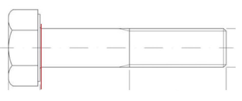
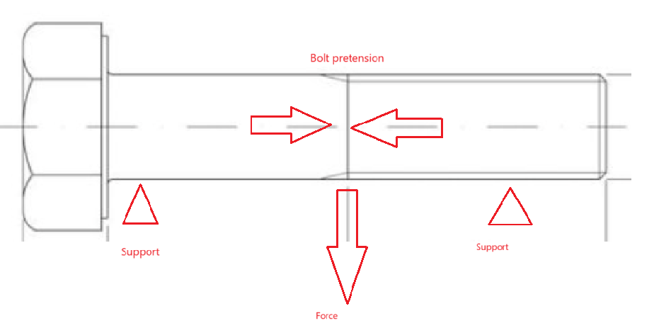
I have recently face a problem with measurement of moment in the bolt radius area (shown on the picture). Bolt is loaded with bolt pretension and force which causes bending. Moment was mwasured in ansys workbench with surface option. Coordination system was placed in the middle of cross section and summation was set to defined coordinate system. Model was calculated with large deflection on. Measured moment was estimately 20Nm when in fact to get the same stress results it should be 4 times higher. I checked that creating model of bolt fixed only on one end and on the other i applied tensile force( same as in the bolt preload) and moment. I incresed the moment to the pioint when stress in the notch area was the same as in the calculated model. Do you know by any chance what can cause that? Did you faced something similar befoere? Do you know how measurement by this option works exactly?
I don't have screens from the model. I hope this drowings will be enought.
I hope somebody will show me where the problem might be.
Thank's in advance.
-
November 5, 2024 at 3:10 pm
dlooman
Ansys EmployeeIs the stress that indicates the moment should be 4 times greater the linear variation of the stress through the bolt or does it include the peak stress at the bolt radius?
-
November 28, 2024 at 7:03 am
kennethjoyce549
SubscriberThe discrepancy in your ANSYS Workbench moment calculation could arise from incorrect summation settings, boundary conditions, or mesh resolution. Ensure the chosen coordinate system aligns with the geometry and loading direction, and verify the “Surface” option includes all relevant forces. Large deflection effects may also influence the results, as nonlinearities alter stress distribution. Refine the mesh in the radius area to improve accuracy, and consider running a simplified basketball stars model to validate the method. Additionally, export forces and moments for manual stress verification. Double-check boundary conditions in both models to ensure consistency with your simplified calculation setup.
-
April 2, 2025 at 8:33 am
taylorwin167
SubscriberThe upbeat soundtrack of Papa's Freezeria is a great addition to the atmosphere of the game. It keeps me energized and excited throughout the game!
-
- You must be logged in to reply to this topic.


-
3407
-
1057
-
1051
-
896
-
882

© 2025 Copyright ANSYS, Inc. All rights reserved.


