
-
-
December 31, 2020 at 2:18 pm
Rameez_ul_Haq
SubscriberPlease observe the structure below:
January 3, 2021 at 8:55 pmSubscriberanyone on this one?nJanuary 5, 2021 at 1:54 pmSubscriber,could you please give your views on this issue?nJanuary 5, 2021 at 1:57 pmpeteroznewman
SubscribernIf you have a shaft with two fixed joints to two faces in the same hole, it's logical to me that the first joint takes all the load and the second joint takes none.nJanuary 5, 2021 at 2:06 pmSubscriberBut that doesn't happen if those were not the same hole, but instead two different holes. I mean another body right after the greenish-gray one, also having a hole in there. And the line body is extended and its vertex is also fixedly joined to that additional hole. Then each of the hole will take a portion of the forces and moments. Is it correct, ? [Assume that the extra body after the greenish-gray one, also have the fixed support as like the greenish-gray body].nJanuary 5, 2021 at 3:45 pmSubscribernYour original post shows a shaft between two holes. The torque in the shaft is shown on the element between the two fixed joints. You don't need another joint in the same hole, outboard of the first joint in that hole. You don't need the shaft to extend beyond the fixed joint.nJanuary 5, 2021 at 5:08 pmSubscriber,kindly try to understand what I am trying to imply here. As shown in the figure as well as you mentioned, there is no reason for the loads and moments to go to the third i.e. the last joint since all of them are going to be transferred from the first joint to the second. nSo now, I have two options. First being I create the end vertex of the line body near the origin of the second fixed joint, or I can create the end vertex of the line body at the end of the long hole of the greenish-gray body [assume it is now a single long hole, with no delibrate cut of faces in between as shown in this post]. The former will have a very small length of deformable element built from the origin of the second fixed joint (or to be more precise, the remote point created there) to the end vertex of line body, while the latter will have a large length of that deformable element. Which one is the correct approach? What should be the difference between these two approaches?.January 5, 2021 at 5:14 pmSubscriberSecondly, I want to ask that assume there is beam connection in reality between the three bodies as shown in the picture below:n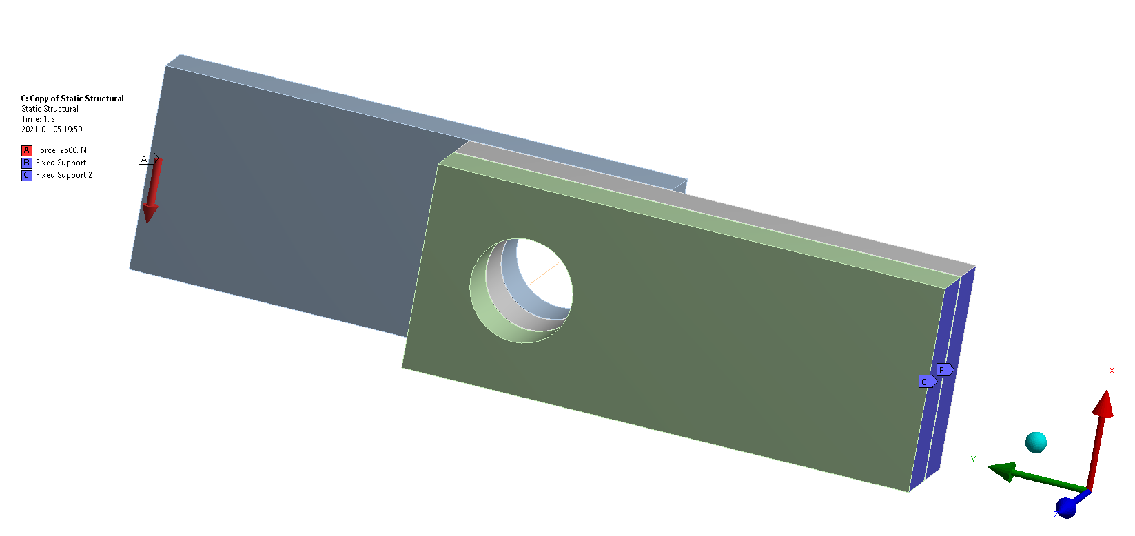 Is it the correct approach to apply a fixed joint to each of the three vertices of the line body to each of the three faces, in order to model a beam? I know I can also directly use the fixed joint between these three faces, but I don't think that would model a beam connection properly since the fixed joints will make the reference face (or faces) to move/rotate exactly by the same amount as the mobile face (or faces). But this doesn't happen in reality since it is possible for the light gray face to have a different amount of movement as compare to the greenish-gray face because of the difference in force and moments transferred to each of them; thats why I wanted to make a line body to model it as a beam between these three bodies.nThere is also an option of beam connection itself in ANSYS, but I am not aware of how can I utilize it between these three bodies.n
January 5, 2021 at 6:49 pmSubscribernWhen using a line body to represent a bolt connecting two plates, the question is how long should the line body be. The answer is it depends on whether it is a nut and bolt or a bolt into a threaded hole. If it is a nut and bolt, then the line body should go the full length of the thickness of the two plates and use a fixed joint at each end to the flat face, not the hole diameter. nIf it a bolt and threaded hole, then the length can be the thickness of the plate with the clearance hole. In this case, the fixed joint to the threaded hole can be the full length of the hole, or the hole face could be divided if the thread depth is less than the hole depth. In either of these cases, if a Bolt Pretension load is applied to clamp the plates together, there must be 2 elements along the line body or the Bolt Pretension load will fail to be created.nWhen using a line body to represent a bolt with pretension used to clamp three plates together, where the bolted joint is designed to prevent slip, the same rules apply as above. There does not need to be any connection of the center plate to the line body. Frictional contact between the faces of the plates prevents the center plate from moving. If necessary, frictional contact could be added between the line body and the hole in the center plate to simulate the case where the applied loads exceed the frictional forces holding the center plate fixed, then contact with the bolt shaft can pick up the excessive shear forces.nUnderstand that Frictional contact will be converted to bonded contact during a Modal analysis, so it would be wise to split a large flat face with a 'washer ring' around the holes so that contact has a limited area.nJanuary 5, 2021 at 9:23 pmSubscriberArray, thanks once again for the details.nCould you please tell what do you mean by the flat face when you wrote If it is a nut and bolt, then the line body should go the full length of the thickness of the two plates and use a fixed joint at each end to the flat face, not the hole diameter. If you can show it in a picture, then that would be so much helpful.nIf it a bolt and threaded hole, then the length can be the thickness of the plate with the clearance hole., didn't quite understood this. A pictorial representation can do wonders here, if you may.nor the hole face could be divided if the thread depth is less than the hole depth.'', shouldn't we only create the fixed joint with the pilot hole, because even if the thread depth is less than the hole depth, that thread depth can include the pilot hole + the clearance hole, but the bolt is not biting into the clearance hole. nif a Bolt Pretension load is applied to clamp the plates together, there must be 2 elements along the line body or the Bolt Pretension load will fail to be created., there are so many things within ANSYS which we refer to as elements, can you please specify what kind of elements you are talking about here ArraynThere does not need to be any connection of the center plate to the line body. Frictional contact between the faces of the plates prevents the center plate from moving., in reality as well? Doesn't the bolt transfer any forces to the hole of the middle plate since it is also biting it?nAssume there is a certain amount of distance between each of the plates, and all of them are connected by a bolt. Then there is no face to face contact. When one plate is applied with a force, the other plates [i.e. the middle as well as the last plate] both experience a force/moment transfer. How do I model this?.January 5, 2021 at 10:10 pmSubscribernWatch the second video in the series here to see an example of a beam element replacing a solid bolt clamping a plate onto another plate that has a threaded hole.n/forum/discussion/1217/bolt-pretension-clamps-two-plates-togethernRead up on Bolted Joint Analysis. nhttps://mechanicalc.com/reference/bolted-joint-analysisnHere is an image from that page:n
Is it the correct approach to apply a fixed joint to each of the three vertices of the line body to each of the three faces, in order to model a beam? I know I can also directly use the fixed joint between these three faces, but I don't think that would model a beam connection properly since the fixed joints will make the reference face (or faces) to move/rotate exactly by the same amount as the mobile face (or faces). But this doesn't happen in reality since it is possible for the light gray face to have a different amount of movement as compare to the greenish-gray face because of the difference in force and moments transferred to each of them; thats why I wanted to make a line body to model it as a beam between these three bodies.nThere is also an option of beam connection itself in ANSYS, but I am not aware of how can I utilize it between these three bodies.n
January 5, 2021 at 6:49 pmSubscribernWhen using a line body to represent a bolt connecting two plates, the question is how long should the line body be. The answer is it depends on whether it is a nut and bolt or a bolt into a threaded hole. If it is a nut and bolt, then the line body should go the full length of the thickness of the two plates and use a fixed joint at each end to the flat face, not the hole diameter. nIf it a bolt and threaded hole, then the length can be the thickness of the plate with the clearance hole. In this case, the fixed joint to the threaded hole can be the full length of the hole, or the hole face could be divided if the thread depth is less than the hole depth. In either of these cases, if a Bolt Pretension load is applied to clamp the plates together, there must be 2 elements along the line body or the Bolt Pretension load will fail to be created.nWhen using a line body to represent a bolt with pretension used to clamp three plates together, where the bolted joint is designed to prevent slip, the same rules apply as above. There does not need to be any connection of the center plate to the line body. Frictional contact between the faces of the plates prevents the center plate from moving. If necessary, frictional contact could be added between the line body and the hole in the center plate to simulate the case where the applied loads exceed the frictional forces holding the center plate fixed, then contact with the bolt shaft can pick up the excessive shear forces.nUnderstand that Frictional contact will be converted to bonded contact during a Modal analysis, so it would be wise to split a large flat face with a 'washer ring' around the holes so that contact has a limited area.nJanuary 5, 2021 at 9:23 pmSubscriberArray, thanks once again for the details.nCould you please tell what do you mean by the flat face when you wrote If it is a nut and bolt, then the line body should go the full length of the thickness of the two plates and use a fixed joint at each end to the flat face, not the hole diameter. If you can show it in a picture, then that would be so much helpful.nIf it a bolt and threaded hole, then the length can be the thickness of the plate with the clearance hole., didn't quite understood this. A pictorial representation can do wonders here, if you may.nor the hole face could be divided if the thread depth is less than the hole depth.'', shouldn't we only create the fixed joint with the pilot hole, because even if the thread depth is less than the hole depth, that thread depth can include the pilot hole + the clearance hole, but the bolt is not biting into the clearance hole. nif a Bolt Pretension load is applied to clamp the plates together, there must be 2 elements along the line body or the Bolt Pretension load will fail to be created., there are so many things within ANSYS which we refer to as elements, can you please specify what kind of elements you are talking about here ArraynThere does not need to be any connection of the center plate to the line body. Frictional contact between the faces of the plates prevents the center plate from moving., in reality as well? Doesn't the bolt transfer any forces to the hole of the middle plate since it is also biting it?nAssume there is a certain amount of distance between each of the plates, and all of them are connected by a bolt. Then there is no face to face contact. When one plate is applied with a force, the other plates [i.e. the middle as well as the last plate] both experience a force/moment transfer. How do I model this?.January 5, 2021 at 10:10 pmSubscribernWatch the second video in the series here to see an example of a beam element replacing a solid bolt clamping a plate onto another plate that has a threaded hole.n/forum/discussion/1217/bolt-pretension-clamps-two-plates-togethernRead up on Bolted Joint Analysis. nhttps://mechanicalc.com/reference/bolted-joint-analysisnHere is an image from that page:n The recommendation is that the grip length in the threaded hole is half the minimum of the thickness or the diameter. That would be a good plane to split the threaded hole so you can scope the fixed joint to that short length of the hole rather than the full length of the hole.nIf there are three plates, there are two clearance holes. The bottom plate has the threaded hole. If the center plate clearance hole is nicely centered, the bolt will not touch the center plate. The top and bottom plates will squeeze the center plate.nA pilot hole is the hole size you drill before you run the tap to cut the threads. You will often see the pilot hole diameter in the CAD model. After the threads are cut, it is called a threaded hole.nIf you draw a line body from top to bottom through the two holes to represent a nut and bolt, it will be meshed with Beam181 elements. If the default mesh size is large it is possible to end up with a single element. That will cause the Bolt Pretension Load to fail to be created. Use a Sizing Mesh Control to force 2 beam elements onto one line body.nIf you have three plates with three holes and want a gap between each of them, you could insert a threaded rod and put a nut on each side of each plate to clamp each plate to the threaded rod. Or you could slide a plain rod through the holes and weld each plate to the smooth rod. To model this, you would create a line body across each gap. Use a Fixed Joint from each vertex to each hole. Maybe you would split the face of the hole in the center plate to have two fixed joints, one for the top plate rod, and the other for the bottom plate rod.n
January 6, 2021 at 7:39 amSubscriberArray, Use a Sizing Mesh Control to force 2 beam elements onto one line body.'', you mean to say that ATLEAST two elements right?nto model this, you would create a line body across each gap.'', you mean to say that a separate line body should be used for each gap, right? Or a single line body passing through all the holes also mean the same thing (with vertices onto the line body, each of it connected to each of the hole).nLet me check out the links that you have shared. I am sure they will be helpful. Thank you nJanuary 6, 2021 at 2:21 pmSubscribernThere is no need for more than two elements, but more than two will not cause a problem.nYes, separate line bodies for each gap.nViewing 12 reply threads
The recommendation is that the grip length in the threaded hole is half the minimum of the thickness or the diameter. That would be a good plane to split the threaded hole so you can scope the fixed joint to that short length of the hole rather than the full length of the hole.nIf there are three plates, there are two clearance holes. The bottom plate has the threaded hole. If the center plate clearance hole is nicely centered, the bolt will not touch the center plate. The top and bottom plates will squeeze the center plate.nA pilot hole is the hole size you drill before you run the tap to cut the threads. You will often see the pilot hole diameter in the CAD model. After the threads are cut, it is called a threaded hole.nIf you draw a line body from top to bottom through the two holes to represent a nut and bolt, it will be meshed with Beam181 elements. If the default mesh size is large it is possible to end up with a single element. That will cause the Bolt Pretension Load to fail to be created. Use a Sizing Mesh Control to force 2 beam elements onto one line body.nIf you have three plates with three holes and want a gap between each of them, you could insert a threaded rod and put a nut on each side of each plate to clamp each plate to the threaded rod. Or you could slide a plain rod through the holes and weld each plate to the smooth rod. To model this, you would create a line body across each gap. Use a Fixed Joint from each vertex to each hole. Maybe you would split the face of the hole in the center plate to have two fixed joints, one for the top plate rod, and the other for the bottom plate rod.n
January 6, 2021 at 7:39 amSubscriberArray, Use a Sizing Mesh Control to force 2 beam elements onto one line body.'', you mean to say that ATLEAST two elements right?nto model this, you would create a line body across each gap.'', you mean to say that a separate line body should be used for each gap, right? Or a single line body passing through all the holes also mean the same thing (with vertices onto the line body, each of it connected to each of the hole).nLet me check out the links that you have shared. I am sure they will be helpful. Thank you nJanuary 6, 2021 at 2:21 pmSubscribernThere is no need for more than two elements, but more than two will not cause a problem.nYes, separate line bodies for each gap.nViewing 12 reply threads- The topic ‘Moment and force transfer within a line body, used to model a bolt.’ is closed to new replies.
Innovation Space Trending discussions
 Top Contributors
-
peteroznewman
 5879
5879 -
scabo
 1906
1906 -
Dennis Chen
 1420
1420 -
javat33489
 1306
1306 -
Shyam Prasad V Atri
1021
Top Rated Tags
© 2026 Copyright ANSYS, Inc. All rights reserved.
Ansys does not support the usage of unauthorized Ansys software. Please visit www.ansys.com to obtain an official distribution.
-


The Ansys Learning Forum is a public forum. You are prohibited from providing (i) information that is confidential to You, your employer, or any third party, (ii) Personal Data or individually identifiable health information, (iii) any information that is U.S. Government Classified, Controlled Unclassified Information, International Traffic in Arms Regulators (ITAR) or Export Administration Regulators (EAR) controlled or otherwise have been determined by the United States Government or by a foreign government to require protection against unauthorized disclosure for reasons of national security, or (iv) topics or information restricted by the People's Republic of China data protection and privacy laws.
