TAGGED: ansys, ansys-fluent, ansys-student, fluent, fluid-flow
-
-
April 24, 2022 at 6:40 pm
chiemezie
SubscriberHello,
I am new to CFD and the use of Ansys Fluent so I am struggling with a lot issues.
Background info: The concept of my design is that, air upstream flows past 3 tanks in tandem of each other and of which one of the tanks is leaking methane gas from the top. The methane gas mixes (no reaction) with the surrounding air as it moves downstream, ultimately, I want to study the changes in the concentration of methane gas in air downwind with time.
I have seen a lot of tutorials simulating flow past cylinders, during which they always cut of the solid cylinder from their fluid domain while the edges of the cut out cylinder serve as the cylinder walls. However, while designing my flow geometry, I did not cutting out the cylinder as I intend to use the cylinder solid body to serve as a flow zone in which I will insert my mass source (modelling the methane gas leak). While meshing the domain, I clearly defined the fluid body under fluid and the solid cylinder bodies under solid. I have already applied the species transport equations while selecting the air-methane gas mixture (no reacting), now my issues are:
- In the Materials dialogue box, under fluid, what should I select there, air or the mixture of air and methane
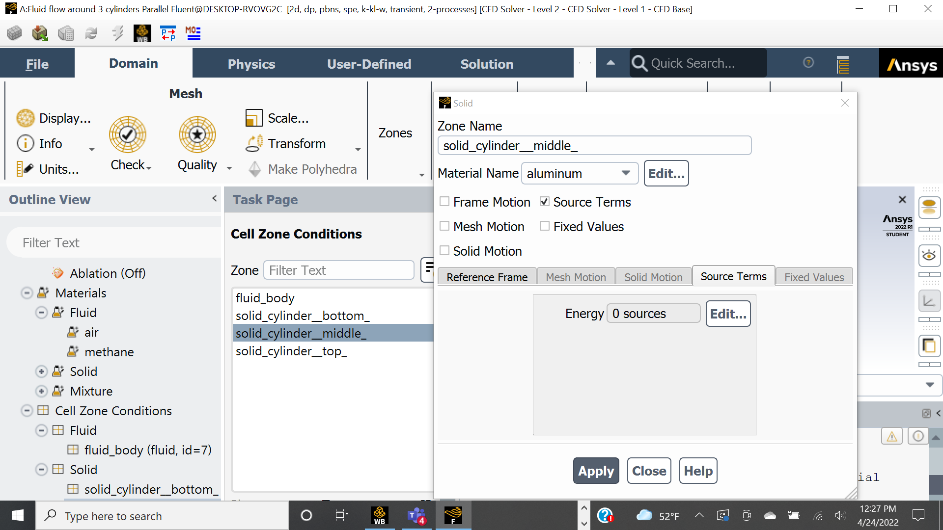
- In the cell zone conditions dialogue box, in setting up the source,, do I set the fluid body (under fluid) to just air or the mixture of air and methane gas? Also, my intention is to set up the mass source term under the solid cylinder body (under solid), but when I did, I only saw the energy term (I expect to see other terms like mass, momentum, etc..). My apologies if I am not clear with my questions, Find attached the screenshots of what I am talking about. If there is any less complicated way to achieve what I intend to achieve, I would appreciate it
- Just as an extra, if you can also help me address the excessive zoom in of my fluent GUI, I will appreciate it, I have tried everything suggested in one of the threads on similar issues but can't seem to resolve it.
Please I need all the help I can in moving forward, thank you so much for your feedback.
April 25, 2022 at 4:22 pmRob
Forum ModeratorThe mixture looks to be OK. You may need to set the fluid cell zone(s) and once you've done that delete air from under the fluid list in materials NOT from under the mixture list! If you get an error check the rest of the cell zones.
As an aside. The only reason to model inside the tank is if you're wanting to model the pressure decrease with time. For an atmospheric model we'd add the methane at an inlet of some form and model the tank as a void.
April 25, 2022 at 4:39 pmchiemezie
SubscriberThank you Rob for your feedback.
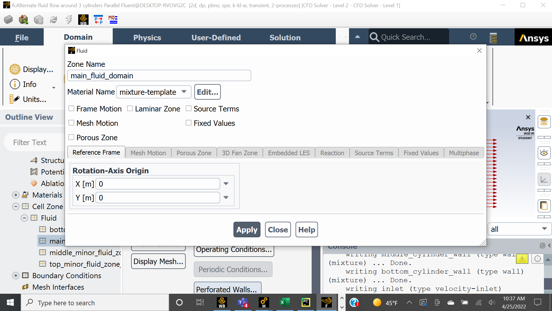
I have set the fluid cell zone(s). Just to be sure, if I delete air from the fluid list, that leaves just methane, now that begs the question, at the inlet does fluent treat the fluid as a mixture (air and methane) or just air?
Just to be clear, in the cell zone conditions dialogue box, the fluids should be set to the fluid mixture right and not the individual fluids (air and methane)
So, I am not actually modelling inside the tank, I just want to place a mass source indicating a leak of methane gas from the top of the tank into the ambient air and study the behavior of the mixture downstream.
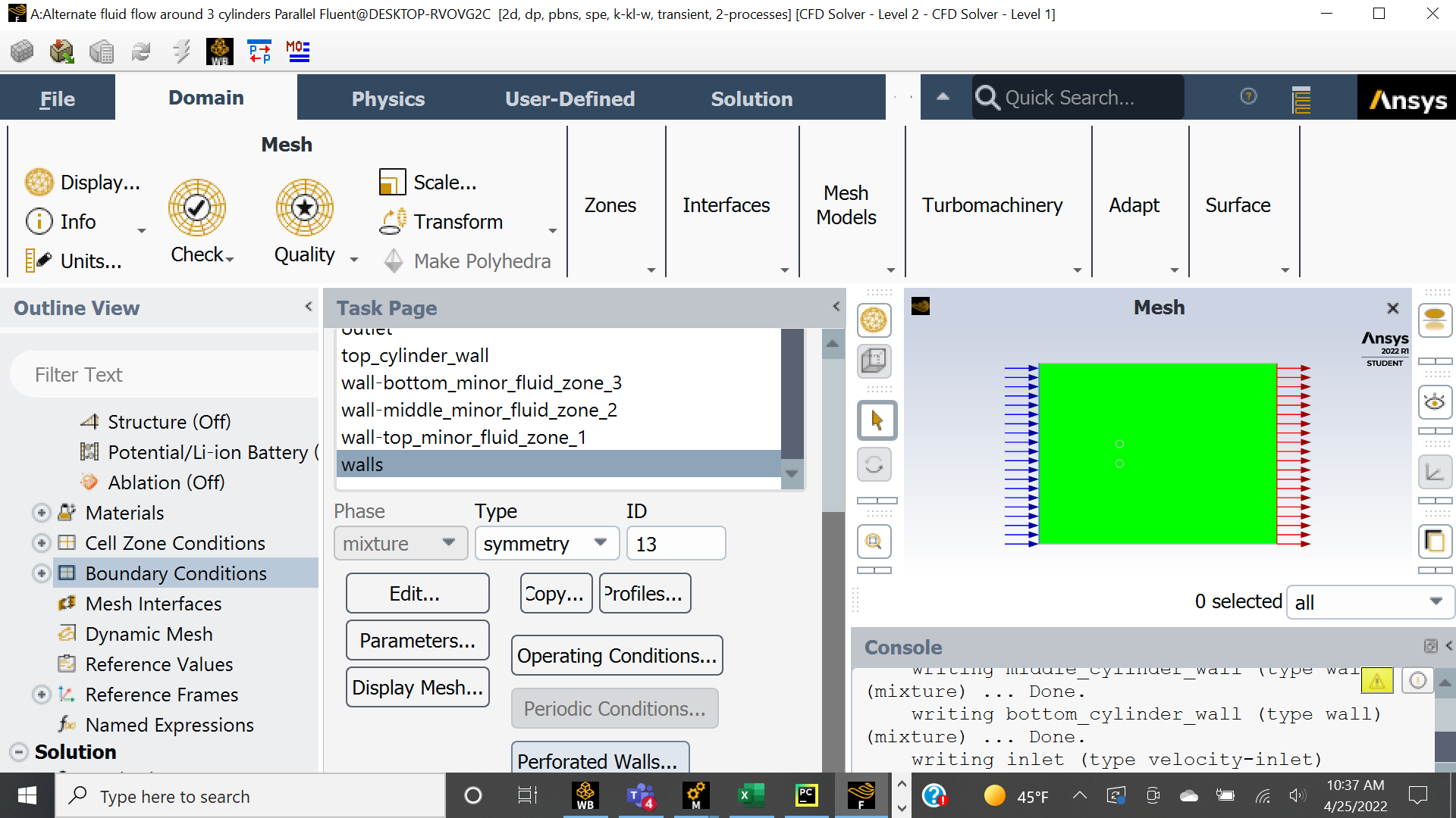
Finally, since I am modelling an atmospheric scenario, not inside a test chamber, I am using symmetry as the fluid domain boundary condition (at the sides of the fluid domain - not inlet and outlet), however, I am not exactly clear on the default pressure or velocity values at those domain edges or do I have to input the values of the parameters up my self. I would want the boundary condition at the sides (up and down) to be atmospheric pressure.
Thank you
April 25, 2022 at 7:19 pmAmine Ben Hadj Ali
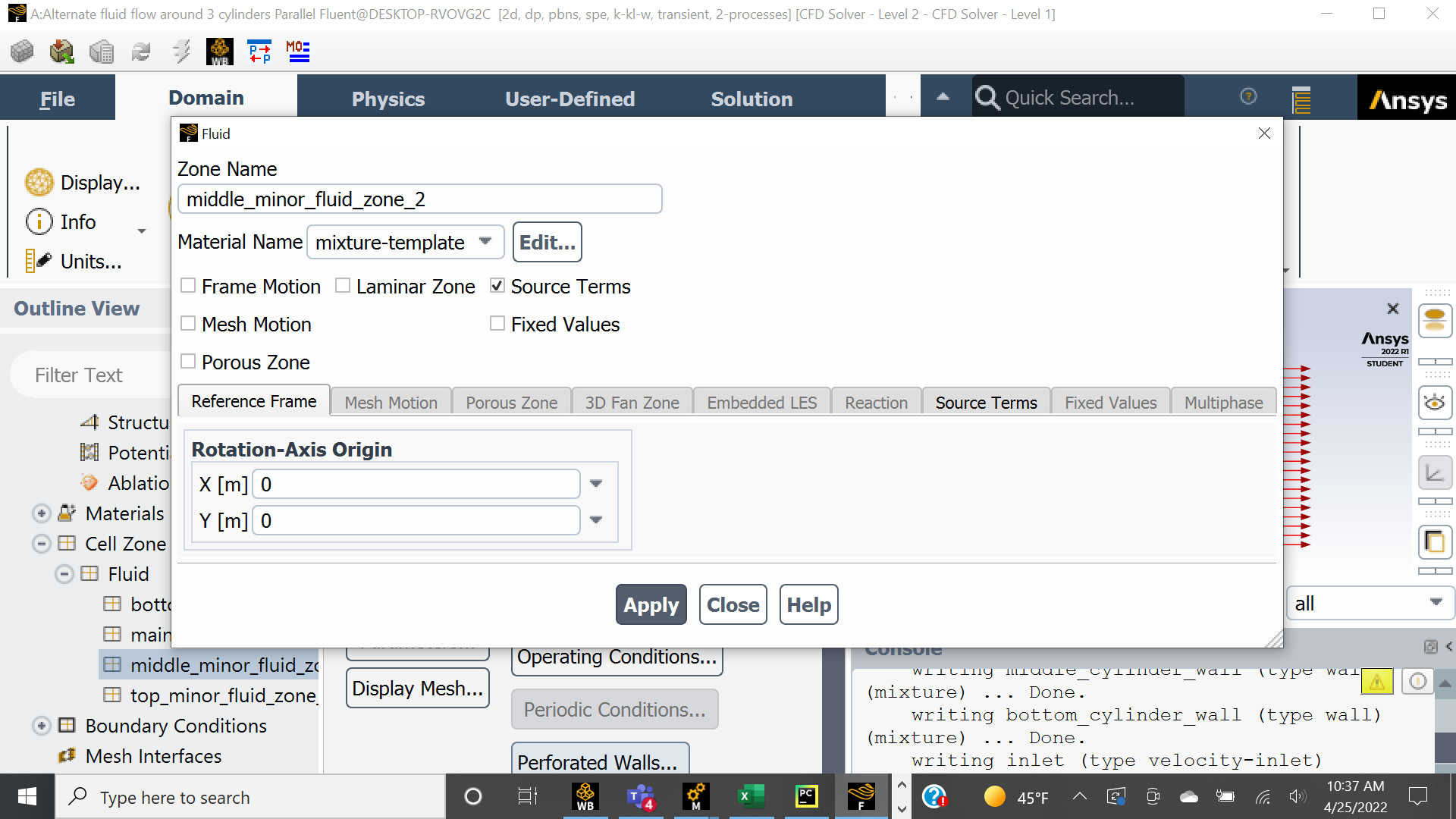
Ansys EmployeeMixture template is the right fluid mixture now for you made of air and methane. Itcseems you have more than 1 cell zone? Is this what you want?
April 25, 2022 at 7:38 pmchiemezie
SubscriberHello DrAmine, thank you for the feedback and help on this.
Yes, because I'd like to place a mass source in any cell zone to simulate leak from a given tank. I am new on CFD and Ansys, do you think it's problematic to have that?
Chiemezie
April 25, 2022 at 7:40 pmAmine Ben Hadj Ali
Ansys Employeeƒæì ƒæî
April 25, 2022 at 7:42 pmAmine Ben Hadj Ali
Ansys EmployeeIf you want to model atmospheric bc just set pressure boundaries to zero gauge pressure and use as operating density the density corresponding to the outside conditions if you have very large domains ( over meters) you mightvrequire other modifications for BC.
April 25, 2022 at 7:49 pmchiemezie
SubscriberThank you DrAmine for you feedback.
Yes I tried setting the BC of the sides of the fluid domain to outlet pressure and it showed directions pointing out of the domain (I became skeptical because I don't know the direction of flow in those areas), so I switched to a wall boundary condition and set the shear stresses on the walls to zero.
Yes my domain is quite large about 86mX115m with the 3 tanks about 4m in diameter with a spacing of about 1m between the tanks.
What do you think?
April 26, 2022 at 2:37 pmRob
Forum ModeratorThat's not overly big, 2500 by 1400 by 350m is getting big.... :) For wind turbine and terrain we may be looking at 5-10km!
Initialise the model to the pressure boundary values (temperature) and report density in the solver. Use that value in the operating density. Then all is well. If the air density is fixed just use that value. You want to use all the significant figures that Fluent reports.
April 26, 2022 at 3:04 pmchiemezie
SubscriberHey Rob, thank you so much for your feedback.
Please how do I initialize to the pressure boundary values? If I get your second point well, you mean I should density solver instead of the pressure solver that I used. Pardon me if I am not getting your point right.
BTW...
I just finished running my simulation and the result doesn't look good. Attached below is the velocity contour, even worse, the air-methane mixture did not work as the mass fraction of methane was zero every where.
These are my simulation parameters, I used:
its a transient model
Used the k-kl-w model since my flow Reynolds number lies in the transition region (5*10^5)
Activated the species transport equation
Activated energy equation
Add my mass source at one of the zones at a constant value (1kg/m-s)
Used constant velocity as inlet BC, 0 gauge pressure as outlet BL and 0 shear stress wall boundary
Used PISO for velocity coupling
Used Presto for pressure
Used 2nd order upwind for the rest.
Used 2nd order implicit time integration
So, I am not exactly sure what is wrong.

April 26, 2022 at 4:24 pmRob
Forum ModeratorPost process in Fluent - it's easier. If you want movies later on then feel free to use CFD Post.
Pressure based solver - you're no where near needing density based. If you do get to that level things have gone very wrong on the tank farm!
I'd not bother with transitional models, if we take a more pragmatic approach, it's turbulent enough to just use k-e or k-w. I favour RNG k-e but there are several arguments for both.
Given the domain size, how long do you think it'll take flow to get from the inlet to outlet? Given time step sizes for a stable solution, can you afford to wait for a "stable" solution? We tend to model terrain & urban flows as steady: note, there are reasons for using transient but as you're learning I'd go steady for speed.
What boundary type have you got between the bulk domain and methane source?
April 26, 2022 at 4:44 pmchiemezie
SubscriberHello Rob, I am super grateful for the responses that you give, thank you so much. I do not know how I would have done much on this project without the help of this forum.
I think I will try the RNG K-e model then.
Given the domain size, a length of about 113.386m and a time step size of 0.0075s (this is because my inlet velocity is 2m/s and the smallest size in my model is 0.015m), It will take about 7559 seconds to travel the length of the domain. In this simulation (the one I shared above) I used (500 time steps X 0.0075s) - I guess that's probably one of the reasons why the contour plot came out that way.
I used a wall BCs on the walls of the cylinder containing the methane source..(oh!! damn!..yeah, because there can't be flow past a wall, the methane gas could not disperse into the main flow domain).. What boundary condition can I use in this area instead of the wall I used there.
I only used transient solution so I can see the behavior of the flow near the tanks but if steady flow can allow me explore that, then I am going with steady state.
I was also considering changing the BC of the side walls from 0 shear stress to pressure outlet
What do you think about these?
April 26, 2022 at 5:21 pmAmine Ben Hadj Ali
Ansys EmployeeAll sides should be pressure boundaries.
April 26, 2022 at 6:33 pmchiemezie
SubscriberThank you DrAmine for your feedback. I will try that
Regarding Robs question on "What boundary type have you got between the bulk domain and methane source"? I used a wall BCs on the walls of the cylinder containing the methane source..(oh!! damn!..yeah, because there can't be flow past a wall, the methane gas could not disperse into the main flow domain).. What boundary condition can I use in this area instead of the wall I used there.
What do you think?
April 26, 2022 at 7:51 pmAmine Ben Hadj Ali
Ansys EmployeeYou csn still use wall but define the methane flux at the wall or volumetric source term in first cell layers of the wall.
April 26, 2022 at 7:54 pmchiemezie
SubscriberThank you DrAmine Please how do I any of that?
April 26, 2022 at 7:58 pmAmine Ben Hadj Ali
Ansys EmployeeLook into Fluent User's Guide to cell registers to cover first cells offcthe wall or to provide flux values for species.
April 27, 2022 at 12:40 amchiemezie
SubscriberHello DrAmine I have created the cell registers one cell off the cylinder walls but I do not know how to insert a source term in these cells (like I would have done if they were under cell zones). Also, how do I calculate the volume of the cells?
April 27, 2022 at 5:23 amAmine Ben Hadj Ali
Ansys EmployeeYou can access the cells registers in Expression to say if I am in cell register I have a source term elsewhere is then zero
If(register, value, zero) fir sure with appropriate unities. To get the volume you do a sum cell volumes if you are in the registers otherwise zero.
Cell register is a boolean.
Do not forget to have the source term applied for bulk too.
April 27, 2022 at 5:36 amchiemezie
SubscriberHello DrAmine, thank you so much for the feedback.
I don't think I understand you especially "applying the source term for bulk too".
Thus far, what I have been able to do is to create cell registers of one cell close to the cylinder wall boundaries, then I used those cell registers to create new cell zones by separating the cell zone around the cylinder walls. I now added a source term in one of the cell zones to simulate the methane gas leak. Does that seem reasonable? Did I capture "applying the source term for bulk" that you were referring to?
Finally, can you explain more on calculating the cell volumes, I have read a couple of threads but was not clear.
April 27, 2022 at 10:53 amRob
Forum ModeratorThat's pretty much it. If you look in the source term it's kg/s/m3 ie the mass is per m3 so you need the cell zone volume to make sure you add enough mass. The thermal example is a cpu chip which emits (for example 5W): given the size of the chip the source may be 250,000 W/m3.
April 27, 2022 at 11:38 amchiemezie
SubscriberHello Rob, thank you so much for the feedback Exactly, my challenge now is how to calculate the cell zone volume, I have read threads in which they were discussed but they are not clear to me.
I would appreciate your help on that.
April 28, 2022 at 1:42 pmRob
Forum ModeratorAh, initialise the model and then use the Volume Reports. Yes, it's that simple!
May 10, 2022 at 7:51 amchiemezie
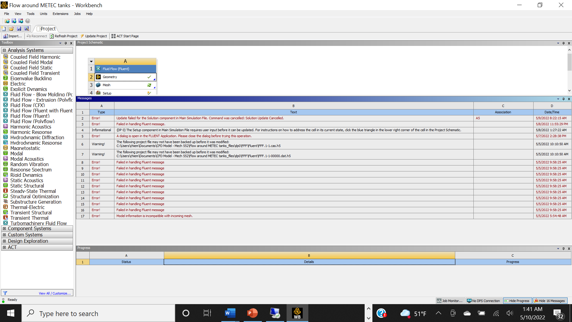
SubscriberHello Rob, so I recently started having this error messages "Failed in handling fluent message" in my workbench after my simulation ends abruptly and fluent closes. I have tried everything but have not been able to fix it, what might be the cause?
So, I decided to use a new machine to run the simulation and it also ended abruptly but I think the reason for this one was that it was out of memory to store results, so I want to know, what is the procedure in copying simulation results while a simulation is still running (i.e. what are the files I need to copy, then delete without interrupting the solution process by fluent?)
Is it possible to run grid study without saving any of the solution at given time steps?
Finally, how I do resume my simulation from the last saved result, my files are saved in ".dat.h5", the last time I tried opening the last saved file in fluent, it did not work.
Thank you
May 10, 2022 at 10:56 amRob
Forum ModeratorIf you export the case and data from the Workbench model try running Fluent as standalone. Also monitor RAM & cpu load. It's relatively rare for Fluent to fail during a run due to the solver, it's far more common (but still unusual) for failures due to running out of system resource. In standalone you can also read/write with sensible labels. You need both the .cas.h5 and .dat.h5 (I always save both at the same time) to resume a run. The case file is the geometry, models, boundary conditions etc; the data file is the results.
May 10, 2022 at 2:34 pmchiemezie
SubscriberHello Rob, yes you did but you left out how to deal with the error messages "Failed in handling fluent message" in my workbench after my simulation ends abruptly and fluent closes. The screenshot is attached. Ignore the set up on my project schematic, have been messing around to know how to resolve the issue.
May 10, 2022 at 4:02 pmRob
Forum ModeratorIf you run standalone we might get a more useful message as the transcript & error files should be retained in the folder you launched Fluent from. Workbench errors tend not to be overly diagnostic as they assume you can check in the tool that's failed.
May 11, 2022 at 8:49 pmchiemezie
SubscriberThank you Rob
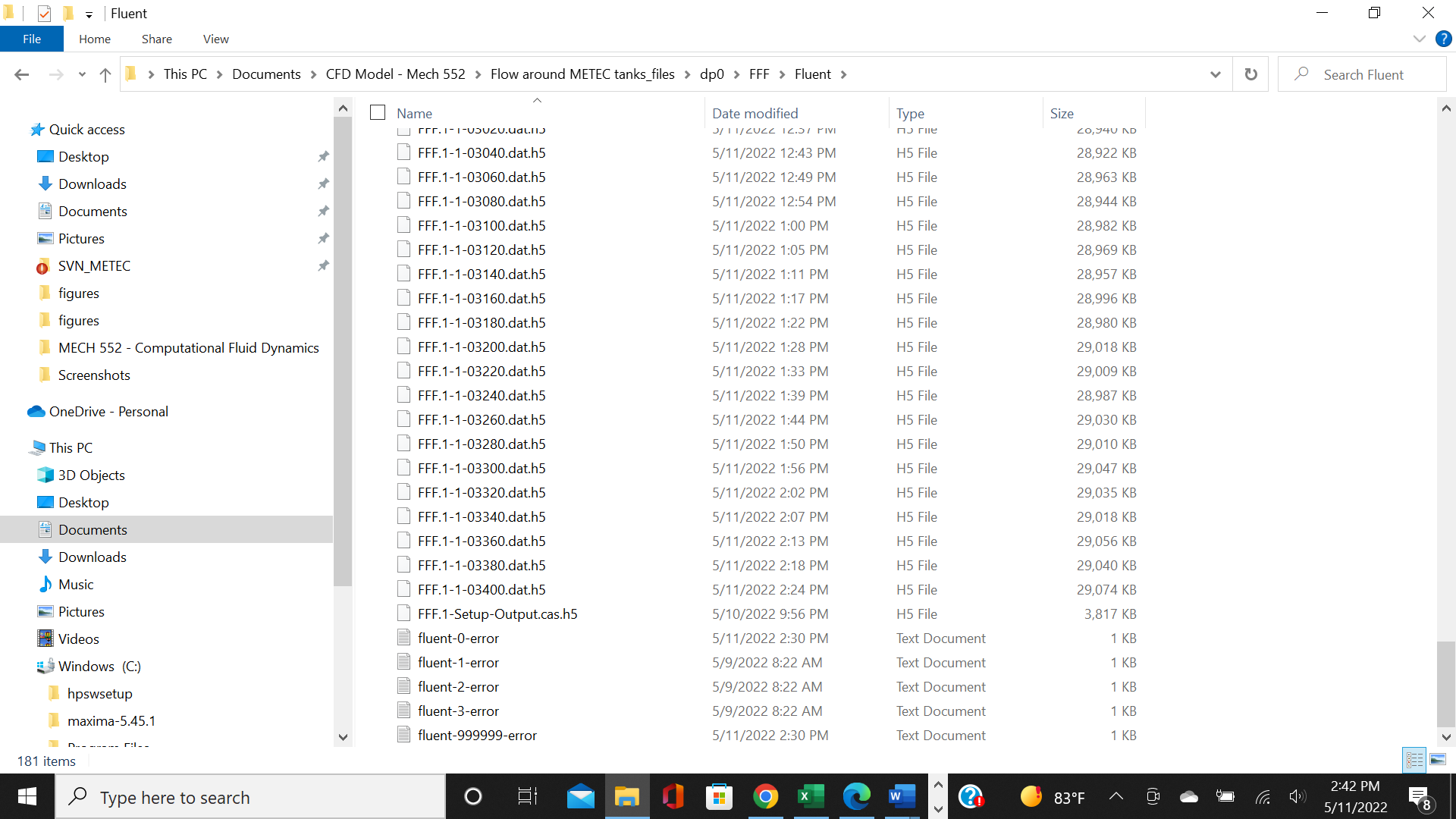
So guys, my simulation ended abruptly again (at about 70% completion), I want to resume it from the last saved result which is saved with the extension .dat.h5 but I am now trying to open it in fluent so to resume from that run but it is not opening, am I doing it in a wrong way? please I need help on this since I need to turn in this project before the end of today. Attached is the screenshot of the last set of results that I have got. Please pardon me for sounding rushy, that's how desperate I am now to get this done before midnight.
May 13, 2022 at 12:53 pmRob
Forum ModeratorBefore doing anything else COPY the contents of that folder somewhere safe. This means that if you mis-click Workbench can't delete all of the data.
In Fluent standalone, first open the case file that's got all of the set up, then open the data file. Once that's done, iterate. Hopefully there's a case file with all of the settings in that folder; if not open the Solution cell in Workbench and export the case file.
Viewing 28 reply threads- The topic ‘Modelling the diffusion and dispersion of gas (methane) leaks from top of tank(s) into air’ is closed to new replies.
Innovation SpaceTrending discussionsTop Contributors-
4833
-
1587
-
1386
-
1242
-
1021
Top Rated Tags© 2026 Copyright ANSYS, Inc. All rights reserved.
Ansys does not support the usage of unauthorized Ansys software. Please visit www.ansys.com to obtain an official distribution.
-

