-
-
November 30, 2022 at 10:10 am
manelaero2020
SubscriberHi all,
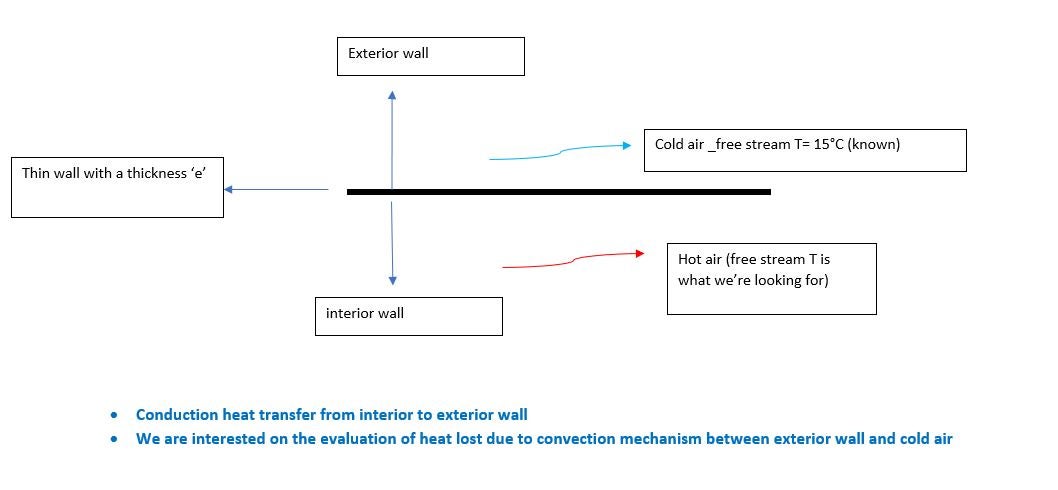
I am modeling the following problem (please see picture ) with Fluent.
What do you think about what I have input (ok? no? more suggestions? )
- for conduction heat transfer through the thin wall,>> shell conduction model, specification of the thickness and number of layers (here 1 layer)
- For convection heat transfer between the outer side of the wall and the cold-free stream,>> the convection model is on with the specification of heat transfer coefficient h and the temperature of the cold-free stream.
I'm very thankful for your assistance
Kind regards
-
November 30, 2022 at 10:42 am
Rob
Forum ModeratorYou only need shell conduction if you are seeing hot spots on the wall, for most applications the flow will convect heat as rapidly as conduction so it's not needed.
Otherwise, yes, a "thin" external wall with a set thickness (you may want to change the wall material from aluminium) with external HTC and free stream temperature is usually a good approach.
-
November 30, 2022 at 10:55 am
manelaero2020
SubscriberHi @Rob ,
Thank you for your response :)
Yes, there are hot spots on the external wall due to significant hot air Temperature ( 150°C)
I'm more sure now of the approach: shell conduction for HT through the wall and convection HT for exchanges between the external side of the wall and the cold-free stream
-
November 30, 2022 at 11:08 am
Rob
Forum ModeratorShell conduction is for ALONG the wall in the solid part. A thin wall with a thickness will handle heat passing perpendicular through the wall.
-
September 26, 2023 at 4:28 pm
Rob
Forum ModeratorWall & wall:shadow should be set as Coupled (default option) and you may want to give it a thickness. That means you have a conformal mesh and (should have) heat transfer.
-
September 26, 2023 at 4:44 pm
Rob
Forum ModeratorIf you have a wall & shadow pair then you already have the wall. You can then give it a thickness (only need to do this once) and a material type unless Aluminium (default) is OK.
-
September 27, 2023 at 9:30 am
Rob
Forum ModeratorCorrect, the two labels are the two sides of the wall. You only set the thickness once, and leave the thermal setting as "coupled". You may also want to review shell conduction.
If the wall is truely "external" then you can set a HTC to the outside and a free stream temperature. It depends where you want to end the modelled domain.
-
September 28, 2023 at 7:55 am
Rob
Forum ModeratorAssuming you're just monitoring an area/mass average on the outlet you may be missing some flow features in the domain.
Remember, a residual is a function of the solver error. So, your initial condition could be really good; or (more likely) there's an unresolved flow feature or transient in the solution. For the latter point monitors will pick up more information, as will taking contour/vector plots every 5-10 iterations for 50-100 iterations.
What you may find is the fluctuation/error/something is negligable. I always cover "poor" convergence in training: check monitors, fluxes and residuals. Then think about what each is telling you.
-
September 29, 2023 at 8:26 am
Rob
Forum ModeratorA wall without a shadow only has cells on one side, so the grey and blue surfaces, if external, would be wall with no shadow. Change one of the fluids to solid (you will have to turn off flow boundaries) and see if any walls form or you see any warnings. I'd be surprised if the wall & shadow switched anywhere, but if you have isolated regions it could be correct.
-
September 29, 2023 at 11:02 am
Rob
Forum ModeratorThey're walls so should still be coupled. I don't recommend messing with interface zones at this point.
-
October 3, 2023 at 9:10 am
Rob
Forum ModeratorI'm not permitted to download anything. It's one of the rules staff operate under to avoid any issues with Export Law.
Looking at the images you have a fluid & other zone. So we can see that's working. If there is no difference in result between setting a wall thickness or not, is that because the flow is slow enough that the fluid-wall thermal transport is the limiting step on heat transfer? Remember, the overall heat transfer is a function of fluid1-wall, wall conductivity and wall-fluid2 I can't remember the equation, it's been a while!
-
October 6, 2023 at 3:44 pm
Rob
Forum ModeratorPlease post a contour of temperature along the centre plane cutting the inlet/outlet pipes. You may need to create a separate isosurface of mesh for each fluid zone.
How does the heat flux balance look?
-
October 9, 2023 at 8:43 am
Rob
Forum ModeratorFluent will use what it needs, so around 2-3GB RAM per 1M cells (models, solver settings etc cause the variation) as a rule of thumb.
-
October 13, 2023 at 11:27 am
Rob
Forum ModeratorThat's a parallel error. Was there anything else in the TUI?
-
October 17, 2023 at 12:38 pm
Rob
Forum ModeratorAnd at the top of that list?
-
October 18, 2023 at 1:53 pm
Rob
Forum ModeratorI don't think we have one, the tutorials in Help (or Learning on here) cover most areas of meshing and the solver. How are you for disc space in the working and scratch folders?
-
October 19, 2023 at 1:04 pm
Rob
Forum ModeratorNot sure then. How many cores were you meshing on? Speed up is OK for some cores, but if there are problems try on one.
-
November 24, 2023 at 2:49 pm
王 zhe
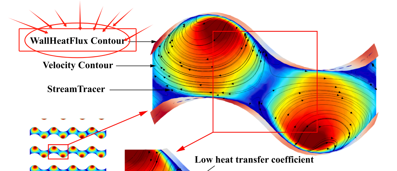
Subscriberanother thing to consult you is how can i see the tpms wall temperature contour in cfd post,i cannot find the true wall so i cannot create the wall temperature contour.
-
November 24, 2023 at 3:25 pm
Rob
Forum ModeratorYou may need to add daat fields to the cdat file, not everything is transferred and some fields are calculated in the Fluent solver as needed. We post process mostly in Fluent too: CFD Post use for Fluent is far less common than 4-5 years ago.
-
November 24, 2023 at 3:29 pm
王 zhe
Subscriberhow can i add data field in dat file for the tpms wall?what shou i add?
-
November 24, 2023 at 3:52 pm
Rob
Forum ModeratorHave a look for the cdat options in File>Export. However, wall temperature might not be an option as it's technically a facet value so switching from the Fluent cell based to CFD Post node based storage may cause issues.
-
November 27, 2023 at 1:49 am
-
November 28, 2023 at 2:10 pm
Rob
Forum ModeratorHeat flux should be available on internal walls too.
-
- The topic ‘modeling heat transfer considering thin wall separating two fluids’ is closed to new replies.


-
3492
-
1057
-
1051
-
965
-
942

© 2025 Copyright ANSYS, Inc. All rights reserved.


