-
-
September 27, 2021 at 6:37 pm
anshuman.kumar
SubscriberHi
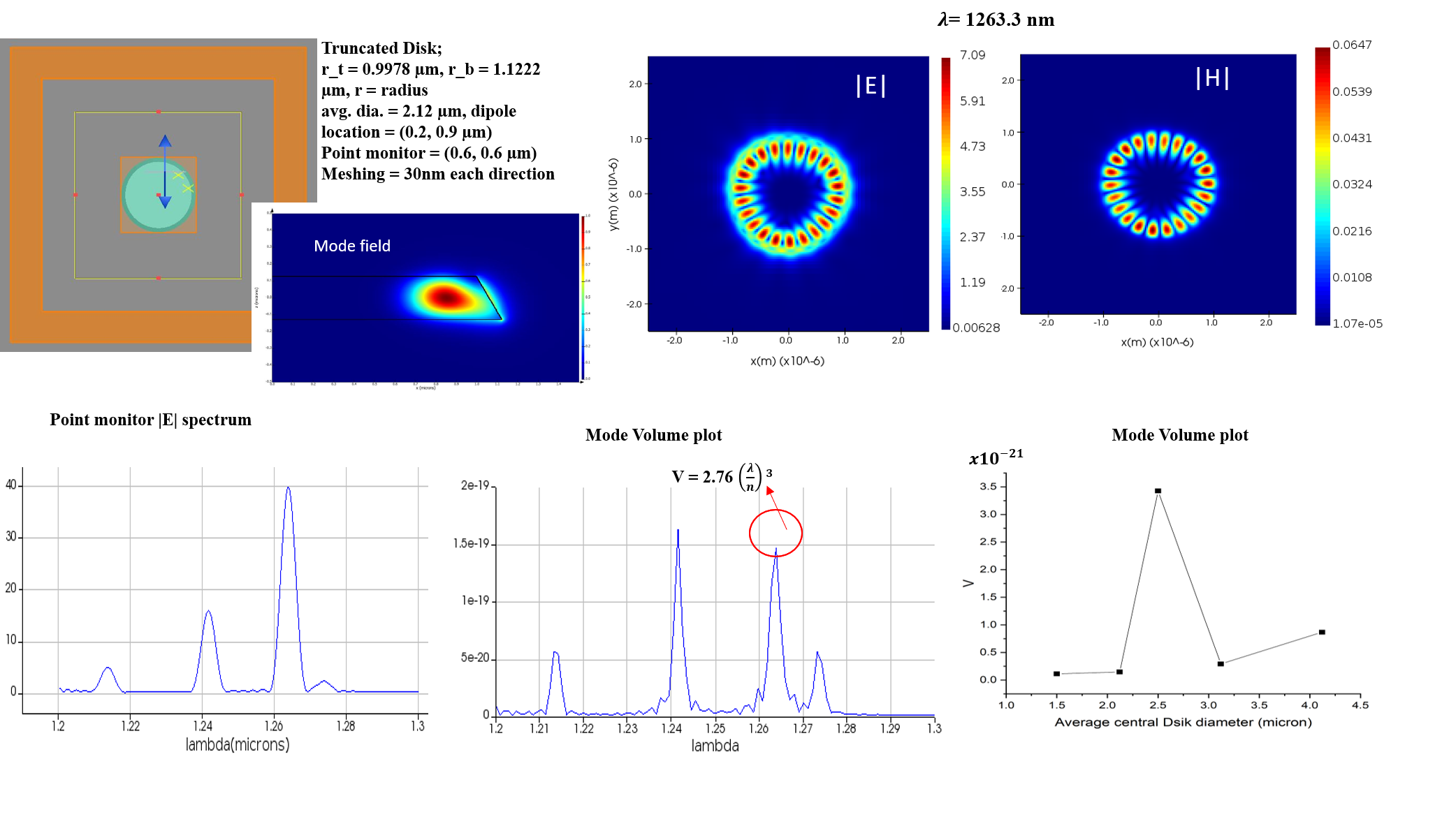
I'm trying to reproduce mode volume calculation of Fig.2a of the paper (https://doi.org/10.1364/OE.14.001094). I used Dipole source as shown in attached snapshot. As paper reported first order radial mode at 1265.41 nm, I obtained cross sectional mode profile somehow same as shown in fig 1a of paper. I obtained WGMs at 1263.33nm and field profile attached in snapshot. as mentioned in paper they took 1200nm band of wavelength in their mode volume calculation (of mode TE_p=1,m=11) with the sweep of truncated microdisk diameter, similarly I followed same to get mode volume by sweeping microdisk diameter and dipole source position but my plot doesn't match with paper.
Mode volume equation used Volume = integral (esp*E2/max(eps*E2)).
few more doubts
(a) simulation at single geometry setup (say at avg. dia. = 2.12 µm, shown in snapshot also) mode volume comes around V = 1.47 e-19 at 1263.33nm peak position but when I do sweep and check at same point its mode volume 1.45992e-21, which 100 times less ?
(b) is the dipole source good choice or some other source (mode source) should be use for mode volume analysis?
September 28, 2021 at 4:08 pmGuilin Sun
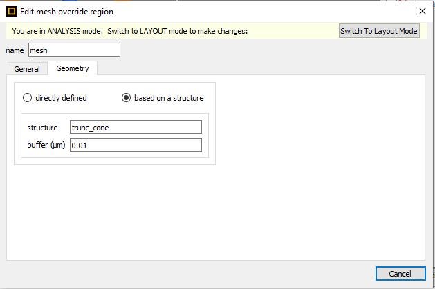
Ansys EmployeeA: when you sweep disk diameter, does the mesh change? I would suggest that you use override mesh to cover the largest disk diameter, so when you sweep the diameter, the mesh will not change. If everything keeps the same, there is no reason to have different result.
B: there is no general guideline to use which type of the source in order to get the maximum mode volume. You can try them and see which gives the largest volume. In General, Dipole source could excite almost every mode, whereas the mode source may excite a fewer modes.
When you try to compare or duplicate, there are many things you need to consider carefully. Please refer this post: Ansys Insight: Why my simulation result is different from published paper or experiment?
September 29, 2021 at 12:57 pmSubscriberA: when you sweep disk diameter, does the mesh change?
reply = based on a structure mesh override region is used (snapshot attached). yes during the sweep mesh dimension (span) change accordingly but mesh step size remain same.
B. When you try to compare or duplicate, there are many things you need to consider carefully.
reply= yeah true, everything chosen similar as paper have reported. I just wanted to simulate the nature of graph of Fig.2a (mode volume plot), i know exact value will not get but trend of plot with minimum error should show. but i my case getting different behaviour.
Doubts:
a) for calculation, paper have used 1200nm wavelength band. how much should I use wavelength span in this band?. In my case, I took 1240 to 1300nm region.
September 29, 2021 at 4:32 pmAnsys EmployeeI would suggest to use ONE single fixed override mesh instead of affiliating with the structure, to cover the largest radius scenario.
1200nm band means from 1200nm to 1300nm? I think it does not matter much, except using beginning wavelength 1200n leads to finer mesh. You may know that the material property plays important roles in getting correct result. Please check.
Once the mesh size is fixed, please sweep the radius in integer number of mesh size.
Viewing 3 reply threads- The topic ‘Mode Volume of Microcavity’ is closed to new replies.
Ansys Innovation Space Trending discussions
 Top Contributors
-
peteroznewman
 3892
3892 -
scabo
 1414
1414 -
Dennis Chen
 1241
1241 -
javat33489
 1118
1118 -
Shyam Prasad V Atri
1015
Top Rated Tags
© 2025 Copyright ANSYS, Inc. All rights reserved.
Ansys does not support the usage of unauthorized Ansys software. Please visit www.ansys.com to obtain an official distribution.
-

Photonics
Topics related to Lumerical and more.
Mode Volume of Microcavity


Ansys Assistant

Welcome to Ansys Assistant!
An AI-based virtual assistant for active Ansys Academic Customers. Please login using your university issued email address.

Hey there, you are quite inquisitive! You have hit your hourly question limit. Please retry after '10' minutes. For questions, please reach out to ansyslearn@ansys.com.
RETRY