-
-
August 22, 2024 at 7:11 pm
Vadym Lozovski
SubscriberI have this simple structure, with the waveguide in red and the electrode in yellow, in MODE FDE with metal boundary conditions. I want to check the loss due to metal. I noticed that when I modify the size of the mesh override region (only a little bit so that the waveguide still stays inside and the simulation region stays enough far) the calculated modes change a lot...why?? I would like to have some personal support because it seems like very specific problem
-
August 23, 2024 at 5:38 pm
Guilin Sun
Ansys EmployeeThis is because by default the mode finding begins from the largest neff, which is mostly inside metal.
You can uncheck "use max index", and specify the original neff data in "n" from the case without the metal.
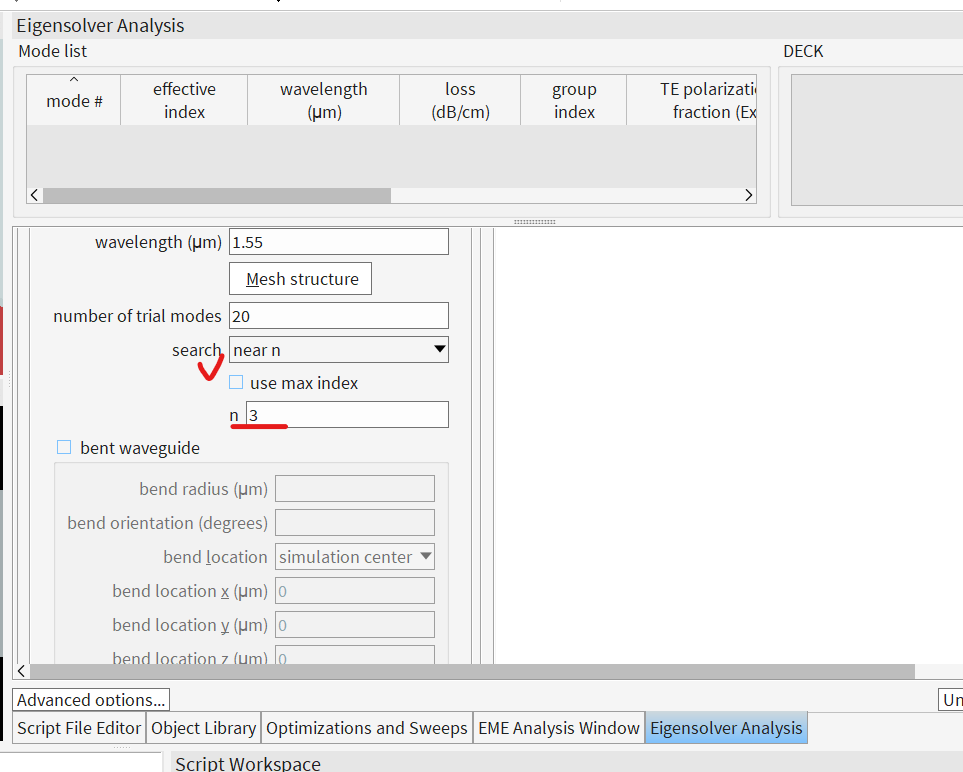
you may also need to set more number of trial modes, since even though you set the "n" at the neff from previous result, it may begin from larger value.
-
- You must be logged in to reply to this topic.
- Difference between answers in version 2024 and 2017 lumerical mode solution
- Import material .txt file with script
- Absorption cross-section of AuNR excited by prism-based TIR
- How to measure transmission coefficients on a given plane .
- TE Polarization Fraction + Waveguide TE/TM Fraction
- Edge Coupler EME Example Issue
- 2D inverse design grating coupler
- Lumerical Python API Topology Optimization Error 2025 R1
- FDE : Simulation waveguides with electrodes
- Loss of lithium niobate phase modulator
-
2577
-
933
-
797
-
599
-
591
© 2025 Copyright ANSYS, Inc. All rights reserved.