TAGGED: apdl, eigen-frequency, modal, rotor, workbench
-
-
September 13, 2021 at 3:47 pm
shubhamop20
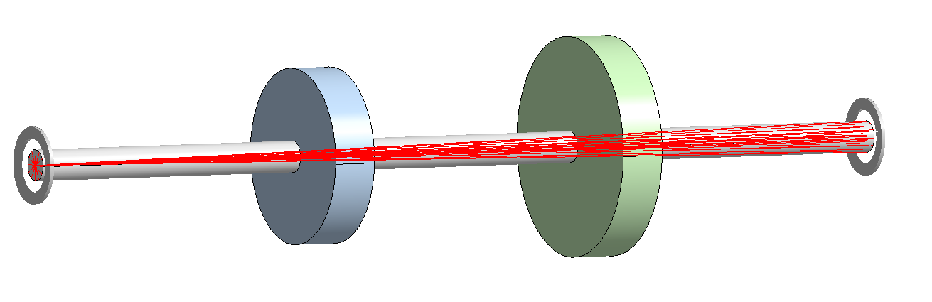
SubscriberI am performing a Modal analysis of a Rotor Bearing system.
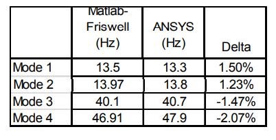
I did the stability analysis by writing my own fem formulation code in Matlab and got the eigenfrequencies and the mode shapes.
Then I performed the Modal analysis using APDL, and the results were in close agreement screenshot attached below.
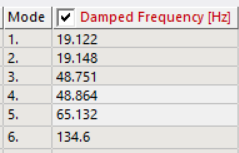
Finally, I did the simulation in Workbench for the same setup and boundary conditions by assuming the solid shaft as a beam element, but the results didn't match.
The problem is that my main setup is quite complex, so that I will be using Workbench; therefore, I was first validating the result for a simple setup, but it did not match at all.
I request ANSYS staff and the users who have worked on such a setup to look into this.
September 13, 2021 at 7:34 pmhesamkeshavarzz
SubscriberHi, Are you sure that you have chosen beam element? its need a command snippet. The meshing is the same as APDL? bye the way, once we assessed the workbench results with matlab for an axisymmetric model, they were quite equal at a specific mesh in workbench.
September 13, 2021 at 9:45 pmBenjaminStarling
SubscriberNot sure about the comment above regarding beam elements, there is no command snippet required to use beam elements.
It appears you have a connections folder with contacts populated in it. I would not model the connection between the solid rotors and the beam elements using contact (if that is what has been done), but in general connecting beam elements directly to solid elements is not ideal. I would recommend using a solid shaft if you are using solid rotors.
Assuming your boundary conditions are correct, this is the only thing that is different between the models.
September 13, 2021 at 11:36 pmSubscriberSorry, you're right, there is no need for command. I think you should use point mass with mass and inertia, instead of the two solid disks.
September 14, 2021 at 9:02 amSubscriber- I again performed the simulation considering the shaft as a solid. I got the following results.
 I don't know where things are going wrong. In the case of Beam formulation, I think you are right contacts are the real problem.
But why considering the shaft as a solid body not giving similar results.
I am attaching the workbench files.
- I tried doing that, but it is giving some weird modes, and the answers are also not matching.
Simulation Files:
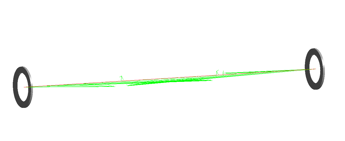
September 14, 2021 at 9:15 amSubscriberYou have a remote displacement scoped to two faces. A remote displacement, as it's name implies, creates a remote point which is constrained to it's scoping. In this instance this constraint is changing the stiffness of your structure. You can either apply two remote displacements, one on each face, ensuring the remote point is in the centre of each face (I did this and got 14 Hz for the first two modes), or use the displacement and fixed rotation boundary conditions.
You can visualise spiders/constraints by selecting solution information, then changing to the geometry tab at the bottom of the main window
 You also still have contacts to connect the shaft to the rotors. I would recommend using a conformal mesh, contacts introduce additional stiffness that can be difficult to account for.
September 14, 2021 at 9:18 amSubscribersame issue with your beam model
September 14, 2021 at 1:11 pmSubscriberThanks a lot, sir problem is solved. Also, I slightly reduced the contact stiffness and got accurate values, as you said.
Grateful for your time and suggestions.
September 14, 2021 at 1:14 pmSubscriberOne last question is it possible to plot orbits using shaft elements in the workbench.
As they are specifically plotted using nodes.
September 14, 2021 at 11:28 pmSubscriberYou can plot orbitals using the PLORB command in MAPDL. I don't think this can be done in Mechanical. This is only applicable to beam and pipe elements. If you are using a solid model you can place a massless and near zero stiffness beam element along the shaft of rotation and use this command.
See section 6.2 of the rotordynamics analysis guide, in the Mechanical APDL help.
Viewing 9 reply threads- The topic ‘Modal Analysis of Rotor Bearing System in Workbench’ is closed to new replies.
Innovation Space Trending discussions
 Top Contributors
-
peteroznewman
 6660
6660 -
scabo
 1906
1906 -
Dennis Chen
 1469
1469 -
javat33489
 1313
1313 -
Shyam Prasad V Atri
1022
Top Rated Tags
© 2026 Copyright ANSYS, Inc. All rights reserved.
Ansys does not support the usage of unauthorized Ansys software. Please visit www.ansys.com to obtain an official distribution.
-