-
-
August 12, 2024 at 8:47 pm
irocha
SubscriberI would like to know if there is a sensor to simulate an integrating sphere. The purpose is to know the color that the light source, in this case LED RGB, has when emitting a certain amount of luminance of each color (R, G and B). Which coordinate is obtained by mixing them, that is why an integrating sphere is mentioned, as a perfect white surface.
-
August 13, 2024 at 7:29 pm
Thomas Martineau
Ansys EmployeeHello,
In Speos, you need to set the sensor to colorimetric or spectral. You can use irradiance (lux at a given distance) or radiance sensor looking to the LED or intensity snesor (by default at the infinite, but you can also set to near field to check closer to the LED).
After the simulation you cna check the color on the result nad if you have set layer to source in the sensor, you cna change the flux of R,G and B independantly and verify the resulting color without relaunching the simulation.
Thanks
Thomas
-
August 13, 2024 at 8:35 pm
irocha
SubscriberHello Thomas,
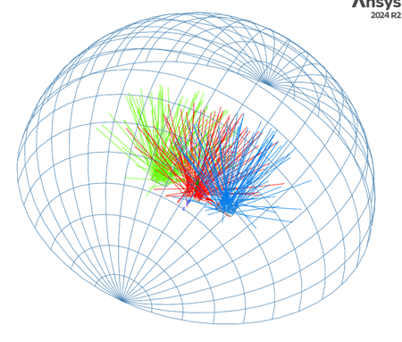
I understand what you are saying, only that when I have the result of the luminous flux emitted by each color, we will obtain red, green and blue spots on the sensor, correct?Â
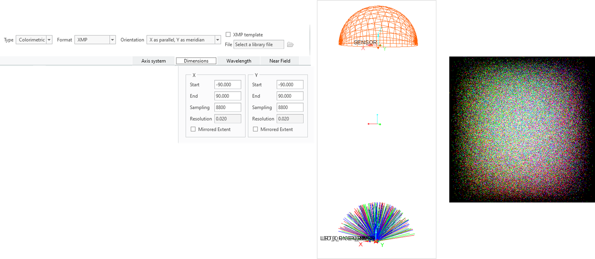
What I am looking for is to know how the fluxes, that I put for each color on the set up, would be mixed, that is why I exemplified the equipment of an integrating sphere since it gives you the mixture of the 3 colors.An extra question, has the capabilities to made Far field sensor in Speos?
Thanks
-
-
August 13, 2024 at 8:55 pm
Thomas Martineau
Ansys EmployeeIt depends on the distance, il you use an intensity sensor at infinite you won't see the spot and you will have the mix color.
In near field you will see the mix at the center and colored spot at the exterior.
Â
For intensity sensor far field (infinite) is the default setup.
Â
ThanksÂ
Â
-
August 13, 2024 at 9:36 pm
-
-
August 14, 2024 at 7:56 am
Thomas Martineau
Ansys EmployeeHi,
When you use an intensity sensor, it's located at the infinite, whatever the distance you see in the 3D view, except if you activate near field.
On the result, there is not enough ray per pixel, your sensor sampling is very high, you can decrease it a lot ! Else you will have to launch much more rays.Â
I did a quick test and this is the result :
Thomas
-
August 14, 2024 at 10:06 pm
-
-
- You must be logged in to reply to this topic.
- STEP File Exports
- Optic studio-zemax operand values are different from the plot (Genc and Denc)
- Assistance Needed for Wavelength Adjustment in Optical Ring Modulator Simulation
- Matlab linkage Zemax memory overflow problem
- Relay Lens Optimization
- Gaussian beam propagation and field by angle
- RMS Spot size in Non-Sequential Method in Zemax Opticstudio
- How to calculate Wavefront RMS when “Remove Tilt” is chosen in Wavefront Map?
- Issues opening Zemax files
- Zemax: creating an array of tilted source
-
2337
-
925
-
599
-
591
-
527
© 2025 Copyright ANSYS, Inc. All rights reserved.