TAGGED: -reflection, simulation, transient
-
-
November 27, 2024 at 2:36 pm
yjpeterpark
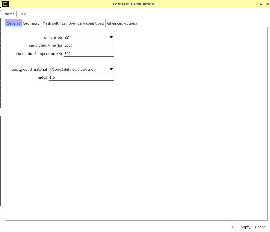
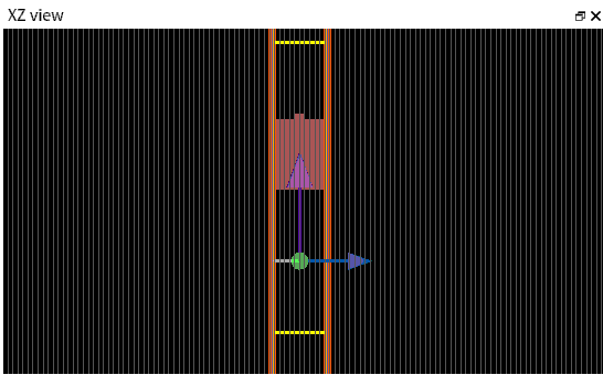
SubscriberI made Silicon metasurface and top silicon is for resonance and bottom silicon is for substrate.
I simulate with 1100nm ~ 2200nm wavelength and I want to check about reflectivity and transmittance.
Top Simulation PML - transmittance monitor - device - source - reflectivity monitor - bottom simulation PML -> each interval is 10um
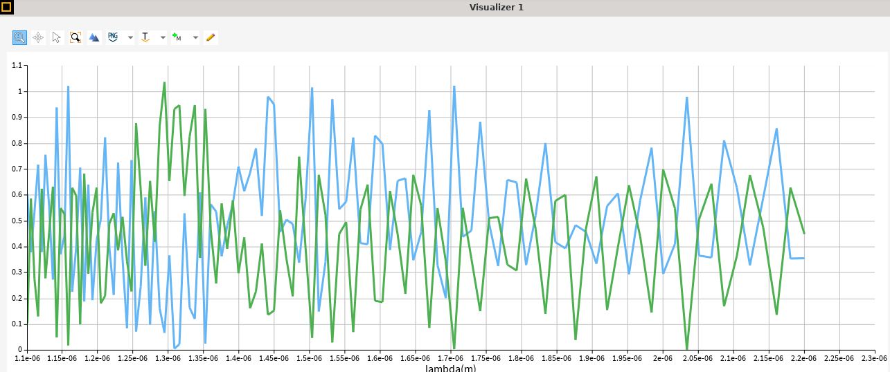
But, when I simulate it, reflectivity and transmittance was greater than 1. And there was big noise.
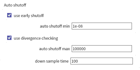
So, I increase simulate time and decrease auto shutoff and add PML layers to 32 with steep angle.
But, result was not change. And mesh was 10nm.
Can you help me about this problems?
blue line is transmittance, green line is reflectivity.
-
December 3, 2024 at 12:46 am
Kirill
Forum ModeratorDear Subscriber,
Your results resemble an undersampled Fabry-Perot cavity with noise. Here are some recommendations to improve your simulation:
- Increase the number of frequency points in your monitor to better resolve oscillations.
- Refer to the article Transmission Results Greater Than One – Ansys Optics. Increase the simulation time, ensure the simulation status equals 2 (indicating it ended by reaching the autoshutoff level), and verify that reflections from PML layers are negligible.
- Perform convergence testing. Follow the Convergence testing process for FDTD simulations – Ansys Optics to minimize numerical errors and achieve reliable results.
Best regards,
Kirill -
December 14, 2024 at 4:58 am
yjpeterpark
SubscriberThank you for reply.
I use your method but it doesn't change result. Reflection and transmission is over 1 and it have big noise yet.
Is normalization necessary in this simulation? It it is, how to normalize reflection and transmission?
Or if you have another method, could you tell me?
Thank you. -
December 18, 2024 at 10:41 pm
Kirill
Forum ModeratorDear Subscriber,
It sounds very strange that you don’t see any changes.
Could you increase the number of frequency points in your monitor, run the simulation, and share the resulting graph?Thank you,
Kirill
-
- You must be logged in to reply to this topic.


-
3427
-
1057
-
1051
-
896
-
887

© 2025 Copyright ANSYS, Inc. All rights reserved.


