-
-
May 5, 2026 at 1:07 pm
guillermo.nunez
SubscriberHi all!
I am studying an assembly with the main part being a Glass Reinforced Sandwich composite. I dont have the ACP module so I cant model the composites that way. After discussing internally we decided not to go with surfaces and shells as we need more detailed information to "manually" (APDL) calculate the puck failure mode.
I have the CAD model with the core and the skins but I am having issues with the mesh. The geometry has very different dimensions, being very thin (20mm inlcuding core and skins) and very long in the longitudinal dimension (12000mm). I would like to have a very structured mesh in order to capture as best as possible the composite behaviour. The idea is to give to each different thickness the composite equivalent strength, while the core is isotropic.
I am trying to sweep the bodies with an structured mesh, but it keeps failing. Ideally, the outer mesh of the core and the inner face mesh of the skins are the same and share the nodes.
Any ideas on how to improve the mesh in these bodies? I am using the Sweep method, face meshing and face sizing. it sometimes work but I would say 10% of the times and when I mesh more bodies it tends to fail. The images shown below show a model which has been sliced in order to simplify the geometry, but I would like to mesh que skin as a whole if possible. I have tried different options for the Src/Trg Selection (Automatic thin, manual thin, Manual source and target...).
Thanks in advance for all the suggestions!
-
May 5, 2026 at 3:09 pm
peteroznewman
SubscriberShell elements such as SHELL181 can be used with layered applications for modeling composite shells or sandwich construction. The shell section commands allow for layered shell definition. Options are available for specifying the thickness, material, orientation, and number of integration points through the thickness of the layers.
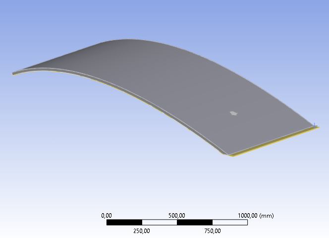
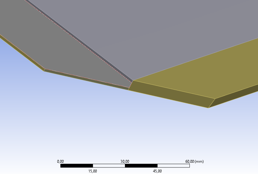
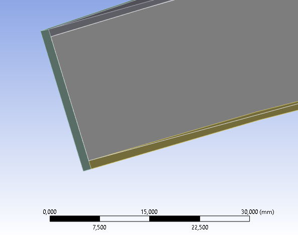
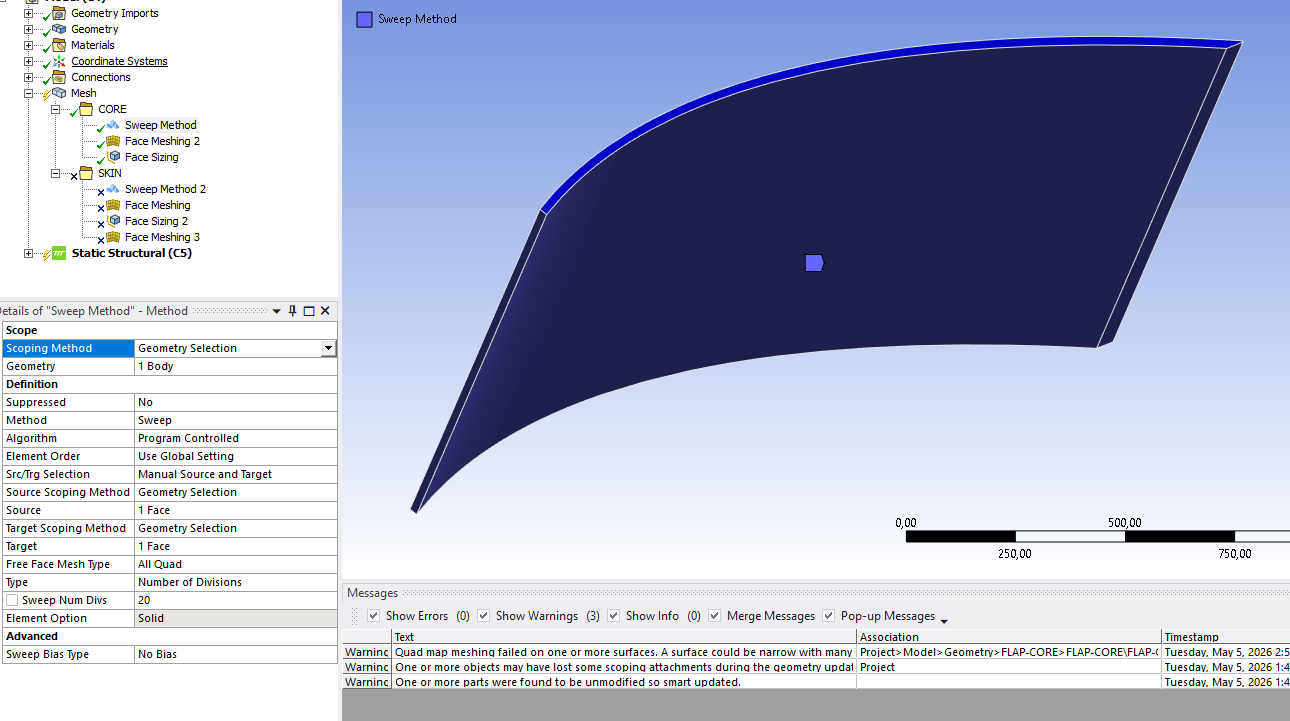
You could start with a simplified global model that only uses SHELL181 elements where the center layer is defined using the core material properties and thickness. However this will not capture the tapered trailing edge accurately. Meshing a core solid with solid elements will give an accurate model of the tapered trailing edge while the skins remain as SHELL181 elements for the fiberglass layup.
A simple way to connect solid and shell elements is to use Shared Topology which guarantees the nodes are shared. Or you can use Bonded Contract if you want to evaluate the bond between the core and the inner face of the skins.
You didn't mention the core material. If it is a honeycomb material you can use Orthotropic properties, if it is a structural foam, use Isotropic properties.
-
- You must be logged in to reply to this topic.
-
6379
-
1906
-
1457
-
1308
-
1022
© 2026 Copyright ANSYS, Inc. All rights reserved.


