-
-
June 19, 2025 at 9:08 am
chavescandinho
SubscriberHi
I am having trouble meshing my wind turbine blades in Ansys mechanical. Despite several attempts, using different element sizes, virtual topology and mesh controls.

My geometry below:
https://drive.google.com/file/d/1OVVvWcjTk-uxtXkYHTrPNVEtYjGcXfPl/view?usp=drive_link
Â
-
June 19, 2025 at 12:58 pm
Govindan Nagappan
Ansys EmployeeRight click on error message and see if it has an option to "show probelmatic geometry"
If it identifies a face or curve, check the mesh settings in this region. Or check the geometry and make sure there are no errors.
From the image, it appears that the mesh is not created on one of the blades. If this is the case, try splitting the blade surface in CAD/Discovery and see if it helps. See if you can split and add edges to show the leading edge surface and trailing edge surface
Â
-
June 19, 2025 at 3:06 pm
-
June 19, 2025 at 11:09 pm
chavescandinho
SubscriberHi @Peteroznewman, I just changed it, so that everyone can have access
-
June 20, 2025 at 12:59 pm
peteroznewman
Subscriber
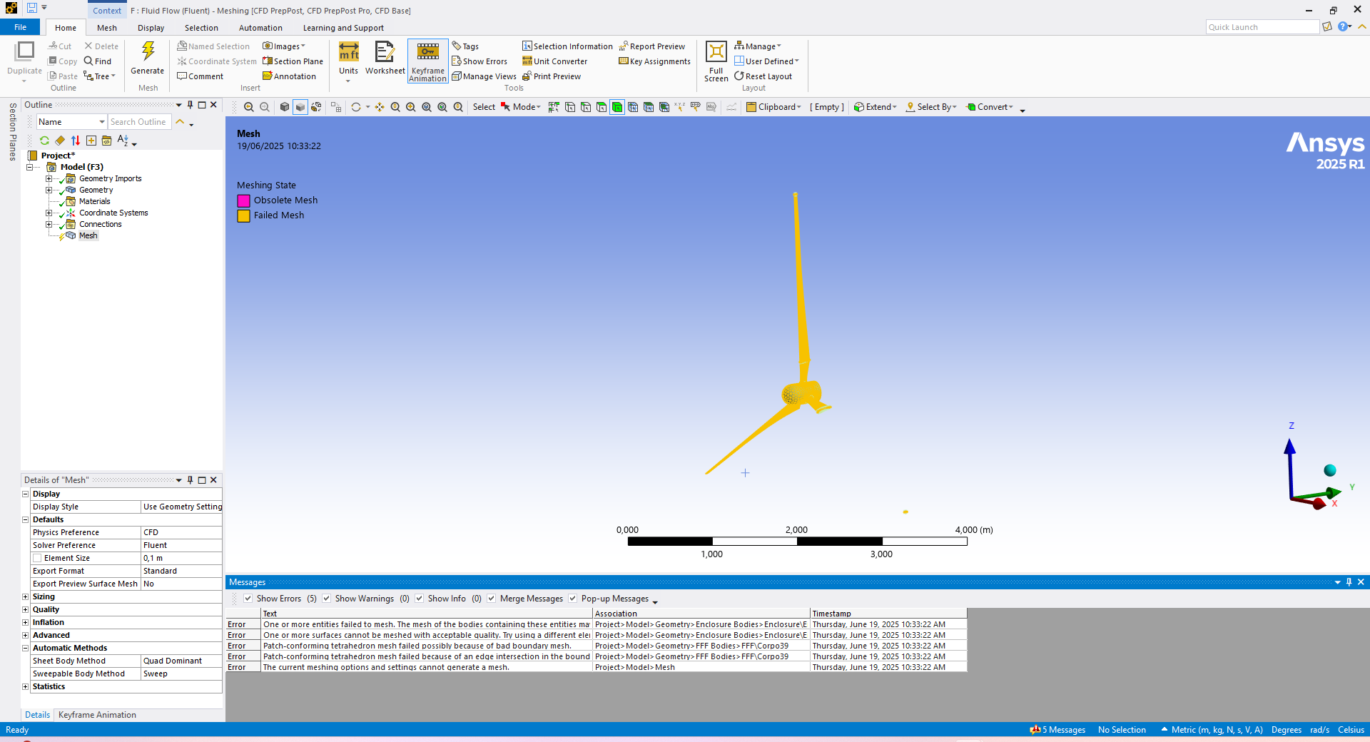
I was able to download the 3 blade turbine. You seem to be trying to mesh the wing solid, but your mesh settings are set to CFD and you appear to be in the Mesh application which is used for meshing fluid domains. Â The normal workflow is to create a fluid body enclosure around the solid parts and create a cavity in the fluid body that exactly matches the solid parts and mesh the air, not the wing.
Please clarify what you are trying to mesh.
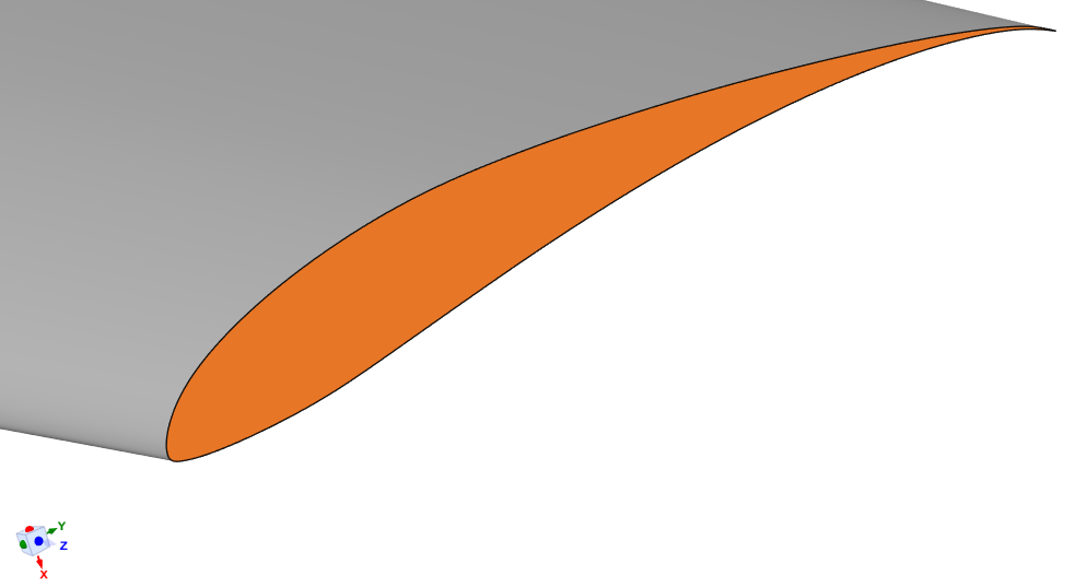
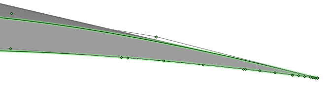
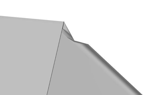
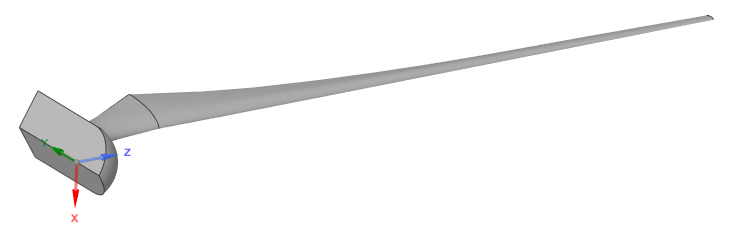
The highlighted face below has a sharp spike which can cause problems while meshing.
It is best to cut that back and Pull the cut face over to the hub to eliminate that spike.
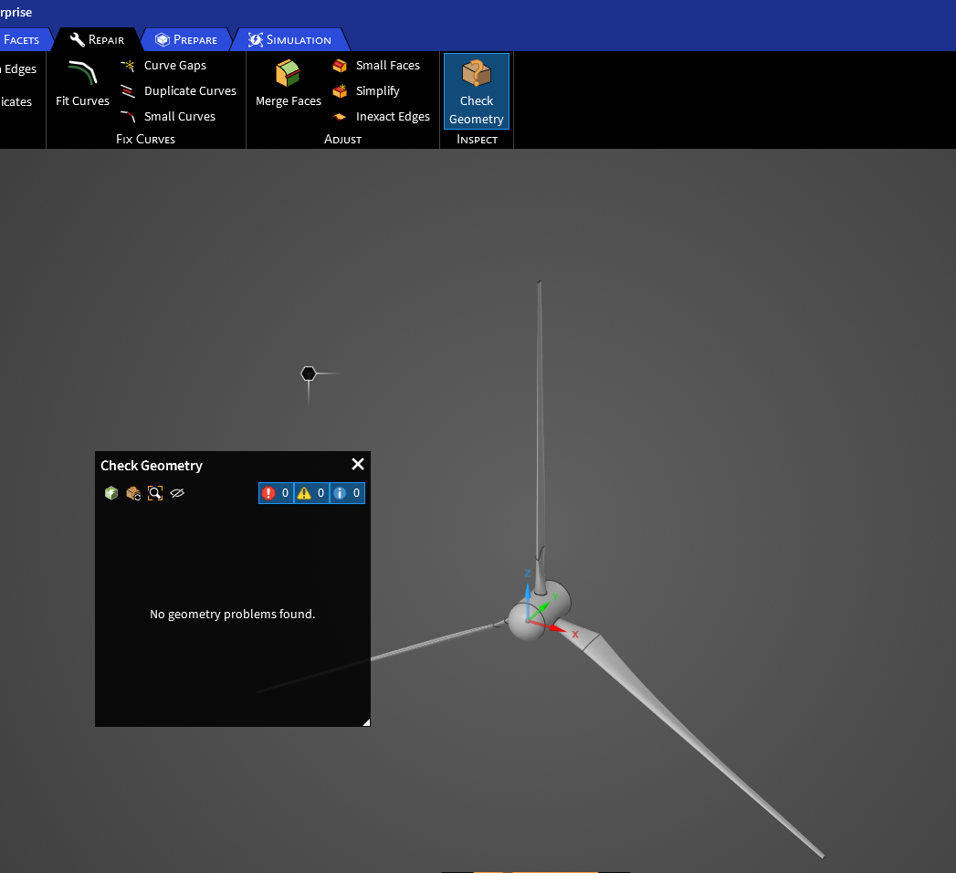
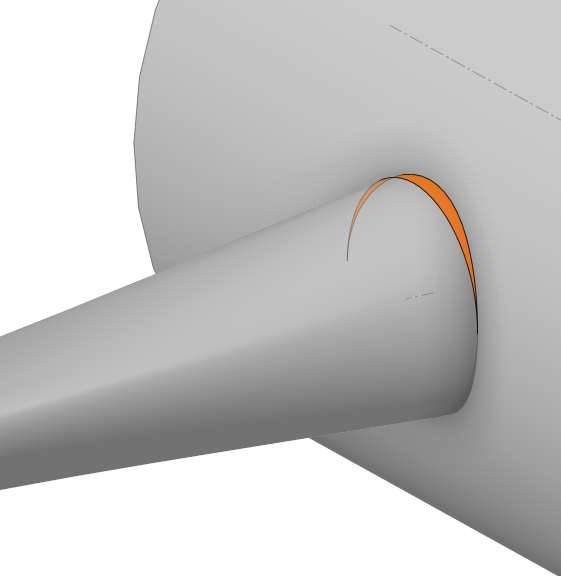
Another defect in the geometry is a row of extra points at this location.
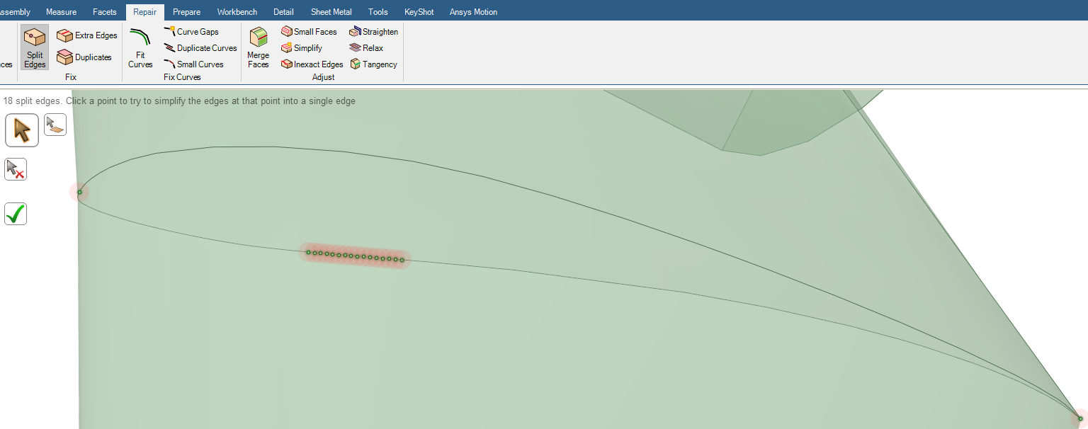
Unfortunately, SpaceClaim can't automatically fix this problem so it will have to be repaired using more manual methods.
Â
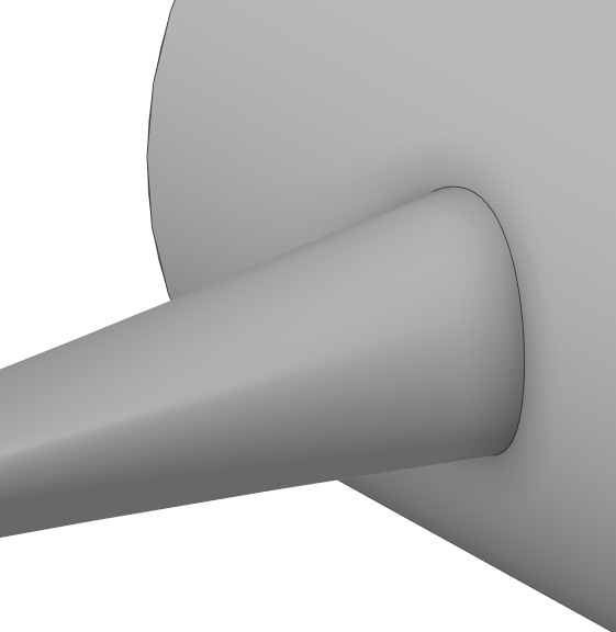
Also, this geometry exhibits periodic property. In some cases, only 1/3 of the full air domain is meshed and periodic boundary conditions are applied to the cut faces of the air domain. Is that appropriate for a wind turbine analysis?
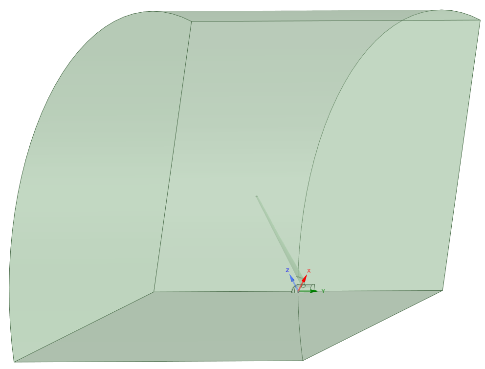
Here is a 1/3 air domain with the blade subtracted. For an accurate simulation result, a much longer downstream mesh is required. I am cutting it off short to save time testing the meshing.
-
June 20, 2025 at 1:55 pm
chavescandinho
SubscriberHi @Peteroznewman, I want to mesh the fluid domain(air) around all 3 blades to analyse their aerodynamic effects on each other. I will create a single enclosure for the full rotor, subtract the blades to form cavaties as you have shown.
for accuracy, I need to simulate all 3 blades since interactions and unsteady effects are important, the sharp spike will be fixed now!
thanks
-
June 21, 2025 at 7:09 pm
peteroznewman
SubscriberI created somewhat clean geometry for a 120 degree air segment. I attempted Fluent Watertight Mesh Workflow. I got this error after surface meshing.
Error: The surface mesh quality is 1 which would lead to a failed volume mesh. Either an un-suitable min size was used or the model contains very sharp trailing edges. In the latter case, it is recommended to add a small chamfer at these edges in the CAD
It is true that the trailing edge is very sharp.
It comes to a point.Â
I recommend taking the advice and adding a chamfer to the trailing edge. This is not easily done in SpaceClaim.
There is also some defects in the surface quality such as the surface near the hub where it joins to the wing.
A clean set of profile curves from the hub to the tip that include a small trailing edge flat may be required to get a good mesh.
-
June 23, 2025 at 5:54 am
chavescandinho
SubscriberThanks, I will apply all recommendations!
-
- You must be logged in to reply to this topic.
-
6379
-
1906
-
1457
-
1308
-
1022
© 2026 Copyright ANSYS, Inc. All rights reserved.


