-
-
October 23, 2023 at 7:06 am
Elena Maier
SubscriberHello,
My question relates to the mesh decisions when defining a semi-elliptical crack.
I studied tha ANSYS Mechanical Handbook, but there are a few questions left:
What exactly does the "largest contour radius"? What happens if I choose it to small or to big, or what would be a good default, if my model is 100mmx100mmx10mm?
How to choose between Tetraedron or Hex-Dominant for the crack mesh, are there pros and cons?
Thank you so much for your help and have a good day. -
October 23, 2023 at 9:50 pm
David Weed
Ansys EmployeeHi,
In general, the crack contour refers to the concentric toroidal volume of 3D elements situated around the crack front nodes. These elements are used to perform the fracture parameter calculations at each node on the crack front (for further information, see the MAPDL Fracture Analsyis Guide 1.2.2.2. Domain Integral Method for Calculating the Fracture Parameters)
In the pic below, you can see 6 concenctric rings, which represent 6 contours (the number of which the user can specify in the semi-elliptical crack settings). The largest contour radius is the length from the center crack front node to the boundary of the last specified contour.
In choosing the radius size, overall you want to make sure that it is of sufficient size to capture the stress gradient around the crack tip. You can also base this radius on the approximate size of your initial crack length. If you are using a tet mesh for the Mesh Method, you will have the option to specify the Front Element Size. If your crack length is 'a', it is recommended to set that size to a/8. You can also experiment with different mesh refinements to see how the results compare. Make sure that the results for contours 3-6 converge. Usually the first two contours will suffer from a lack of accuracy since they are closest to the crack tip stress field.
In the past, a structured hex mesh was required to obtain good accuracy for the fracture parameter calculations. However, using a tet mesh will produce comparable results, especially in light of the Unstructured Mesh Method (UMM) which ANSYS software automatically employs when a tet mesh is present. Note that if you want to perform SMART crack growth a hex mesh cannot be used and you'll need to specify a tet mesh for the Mesh Method option.
-
October 25, 2023 at 11:46 am
Elena Maier
SubscriberThank you so much for your detailed answer.
1.Where can I find MAPDL Fracture Analsyis Guide this guide?
2. So would you prefer Hex mesh for the crack? I tried both, and in my opinion Hex mesh had a faster calculation and similar results.
3. In this case is a the crack length or the second radius "a"? if for example my crack has both radii set to 2mm what would be an appropriate contour radius? I still don´t get why I should choose it bigger or smaller?
Thank you so much for your help.Elena
-
October 25, 2023 at 9:49 pm
David Weed
Ansys EmployeeHi,
- You can access the guide online here: https://ansyshelp.ansys.com/account/secured?returnurl=/Views/Secured/corp/v232/en/ans_frac/ans_frac.html
- If you are only evaluating the fracture parameters, then a hex mesh will be more efficient; it will produce good results using a lower number of elements than a tet mesh. If you are performing crack growth, you will need to use a tet mesh instead.
- We can take the crack length, ‘a’, to be the user-defined minor radius value of the semi-ellipse. The Largest Contour Radius should be set to this value. As a check, you can experiment with going above or below that value, comparing the results from each run. You’ll find that some variation in the largest contour radius parameter is permissible as the respective fracture parameter results should be comparable. Just an additional note: when Mechanical calculates the default Front Element Size (when Mesh Method = Tetrahedrons) you will notice that it produces a value that is roughly equal to the minor radius divided by 10. This indicates that acceptable mesh resolution for calculating fracture parameters is driven by the minor radius value. Some users use a/8, a/10, and in some cases a/20. This will depend on your geometry, loading conditions, and stress field around the crack area. Before doing a large run, it’s a good idea to test these parameters so that you can ultimately set up an efficient run that also produces acceptable results.
-
-
October 31, 2023 at 2:34 pm
Elena Maier
SubscriberHey,
Thank you so much for your help!
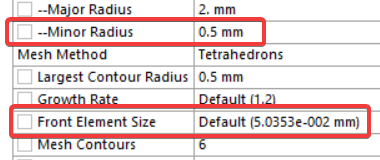
So for my specific example:i use, as suggested, hex mesh for my halfelliptical crack and my parameters are:

and my minor radius (zweiter Radius) is 2mm you would suggest a largest conour radius of 2mm?
Besides the fact, that the contour line 6 touches itself in the middle then?
Sorry, but I still don´t understand what happens when using to "big" or "small" radii. And how to determine the right radii.
(and unfortunately my supervisor does not no the licence number yet, so I can´t use the support link from 1.)
I already tried different radii and some didn´t work, since to big or the run time was unefficient, but between 0,2mm and 1,5mm the stress intensity factor was almost the same (And I only want to know K (SIFS)).
-
- The topic ‘meshing a semi-elliptical crack’ is closed to new replies.


-
3432
-
1057
-
1051
-
896
-
892

© 2025 Copyright ANSYS, Inc. All rights reserved.


