TAGGED: #acp-#compositematerials, #compositematerials, foam, taper
-
-
January 10, 2025 at 4:42 pmariel.lustySubscriber
Hi all,
I'm trying to model a quadratically tapered composite beam in Ansys Composite PrepPost. The shelled beam looks like this:
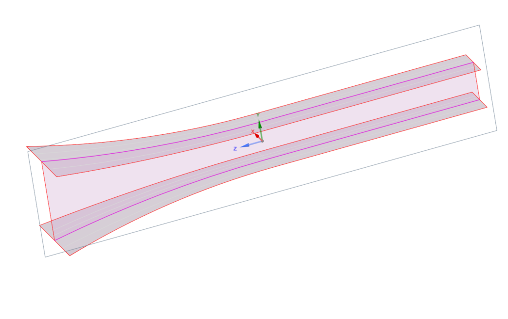
I want the cross-section to look like the figure below, where the blue lines are unidirectional plies, yellow are adhesives, red are biaxial plies, and green is foam.Â
Unfortunately, when I'm modeling the web, the plies on the right are passing through the foam.Â
Does anyone know how I can make it so the plies do not pass through the foam?
Kind regards,
Ariel
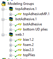
Also, there are the modeling groups if that's helpful at all.Â
-
January 14, 2025 at 11:52 amRaman BabuAnsys Employee
Hello Ariel,
Have you looked at the ACP workshop example on  T-Joint? It is similar to your case." If you have not checked it, please review it once.
Since you are generating solid elements, please keep a coarser mesh around the corner region. Also, it should be larger than the thickness of a ply otherwise solid corner elements may intersect each other.
Regards,
Raman Babu
Â
Â
Â
Â
-
- You must be logged in to reply to this topic.
- At least one body has been found to have only 1 element in at least 2 directions
- Error when opening saved Workbench project
- How to apply Compression-only Support?
- Geometric stiffness matrix for solid elements
- Frictional No separation contact
- Timestep range set for animation export
- Script Error Code:800a000d
- Image to file in Mechanical is bugged and does not show text
- Elastic limit load, Elastic-plastic limit load
- Element has excessive thickness change, distortion, is turning inside out
-
1441
-
599
-
591
-
591
-
366
© 2025 Copyright ANSYS, Inc. All rights reserved.