TAGGED: 3D-Transient-Thermal, apdl, meshing
-
-
August 13, 2024 at 8:37 pm
Leon15
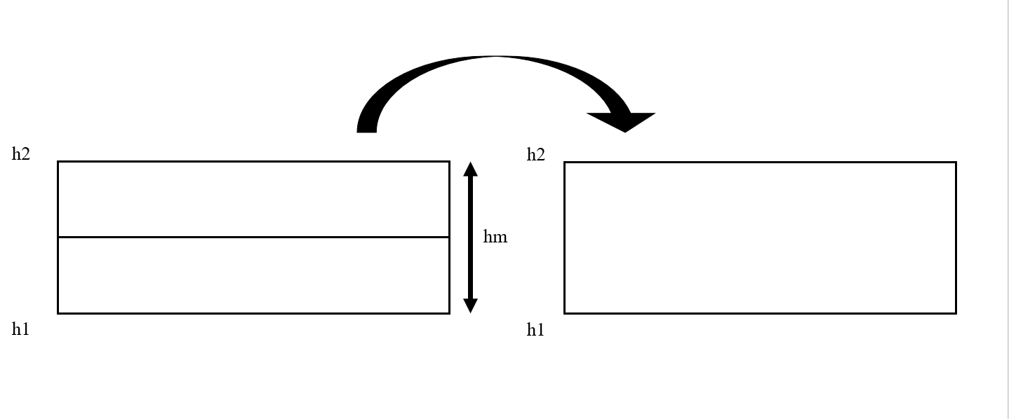
SubscriberHello, I am working on a mesh coarsening algorithm for a thermal transient simulation using ANSYS APDL. The concept is pretty simple as the calculation progress, groups of 2 layers of elements are merged together. Currently I am running a simplified case to test my code and everything is working proprely until the third group meshing. Indeed, a new volume is created with equivalent thickness to the two layers of element meshed (deleted prior the creation of the new volume), but it fails to be meshed. Further more when I use the NUMMRG and NUMCMP commands to merge the nodes I get the warning: Due to merge, line xx is now meshed. Here is a brief summary of the command I am using and a schematic:
h1=0.0021h2=0.0031hm=0.001VSEL,S,LOC,Z,h1,h2eslvnsleVCLEAR,allVDELE,all, , ,1ASEL,S,LOC,Z,h1LSLAVEXT,all, , ,0,0,hm,,,,MSHKEY,1VSWEEP,ALLALLSELNUMMRG,ALL,1e-5, , ,LOWNUMCMP,ALL
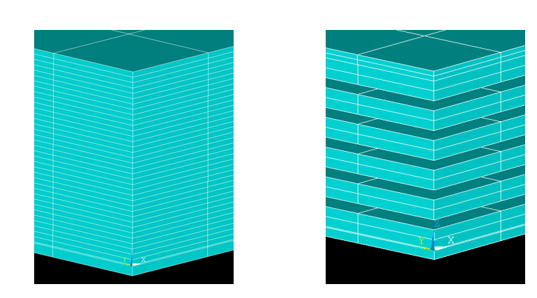
I am a bit puzzled as of why it is working for the first 2 group meshing, but not the third.The picture below show my model before remeshing and after for 18 layers. I can also provide my entire code for testing if needed.
Thanks a lot,Leon -
August 19, 2024 at 3:00 pm
dlooman
Ansys EmployeeThere's a risk when intermingling solid modeling with meshing that the associativity between the mesh and the solid model gets corrupted. If there's any way to modify your procedure so that the mesh is completely cleared before modifiying the solid model that would be safer. There's also the possibility that a too loose tolerance on the nummrg command merged out a line.
-
August 19, 2024 at 4:12 pm
Bill Bulat
Ansys EmployeeHi Leon,
Dave raised some good points. Actually, if I were to attempt such a thing I might even stick to direct generation and leave solid modeling out of your mesh coarsening procedure. But before diving into details on how that might be done, I have a concern...
You mentioned doing this coarsening procedure "as the calculation progresses". Do you mean you intend to do it while the solution executes? I didn't know such a thing was possible. Once the system matrices are formed at the beginning of the solution (based on the initial mesh), I'm quite certain that the model can't be changed in this manner. There are features with functionalities similar to what you are attempting - element birth and death and nonlinear adaptive meshing come to mind - but if I understand your objective correctly, I don't really see a way to change the model (elements, mesh, nodal connectivity) during solution.
If might help if you can tell us the reason you want to coarsen the mesh during a thermal transient. For some reason your description reminds me of an idiosyncracy not uncommon to thermal transients in which boundary conditions change suddenly (thermal undershoot/spurious oscillations). Among the tricks for addressing the occurence of thermal undershoot is refining the mesh in the depth direction at the surface experiencing the sudden change (the mesh is typically coasened with increasing distance from the surface, rather like "inflation" meshing that the CFD folks use to resolve steep field gradients at no-slip surfaces). Does the reason you want to do this have anything to do with sudden exposure to severe thermal boundary conditions?
--Bill
-
August 19, 2024 at 4:38 pm
Leon15
SubscriberHello,
Thanks for the quick and comprehensive replies. So to clarify what I mean with “as the calculation progresses”, my current approach is to exit the /solu processor and coarsen the mesh in the /prep7 processor before going back into the /solu processor to pursue the calculation. The nodal temperature are saved in an array and re assigned between the different /solu steps. So far this approach prove to be very unefficient because of all the read and writting involved to transfer the results between the different /Solu. To give a bit more background I am simulating an additive manufacturing process involving the deposition of layers of material, for that, the element birth and death technique is used. I am trying to explore the possibility of using a finer mesh at the top surface of the model, but my challenge is that the top surface changes over time due to the activation of new element layers. As of right now the model is created with a refined mesh and the central elements are coarsen as new layers are deposited.
-
- You must be logged in to reply to this topic.


-
3467
-
1057
-
1051
-
929
-
896

© 2025 Copyright ANSYS, Inc. All rights reserved.


