-
-
November 7, 2024 at 3:19 pm
jaafar.elwati
SubscriberHello everyone,
I have a problem with the VPWM source in Maxwell circuit. I define all the parameter and when I simulate, it gives me a sinusoidal signal with a triangular ripple.
The results that I expect from a PWM source is to give me a square wave signal while comparing a control signal that is sinusoidal with carrier signal which is triangular.
Anyone can help me with this problem?
And thank you.
-
November 19, 2024 at 3:43 pm
Tamami Yamanaka
Ansys EmployeeHello,
Ensure that parameter settings for the VPWM source are set correctly. Also, verify that the Type parameter is set appropriately to TIME or POS, depending on whether your output signal is a function of time or position.
Maxwell Help > Using the Maxwell Circuit Editor > Components > PWM Voltage Source:
Ansys Maxwell 2024 R2 – PWM Voltage Source
-
December 29, 2024 at 2:35 am
mitelectrical15384
SubscriberHello everyone,
I have a problem with the VPWM source in Maxwell circuit. I define all the parameter and when I simulate, it gives me a sinusoidal signal with a triangular ripple.
The results that I expect from a PWM source is to give me a square wave signal while comparing a control signal that is sinusoidal with carrier signal which is triangular.
Anyone can help me with this problem?
And thank you.
-
December 29, 2024 at 2:38 am
mitelectrical15384
SubscriberTamami Yamanaka please provide sample settings of parameter to get proper pwm signals. so, I can understand the mistake I am doing in parameter settings. Thank you.
-
December 29, 2024 at 1:16 pm
Tamami Yamanaka
Ansys EmployeeHello,
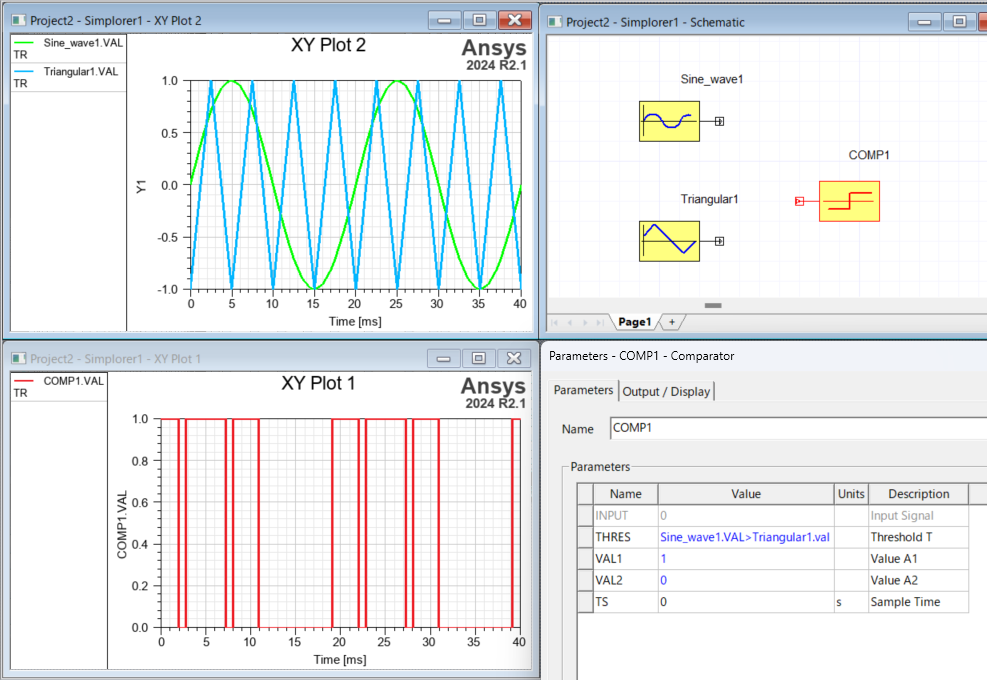
I apologize for misunderstanding your question in my previous response. The VPWM source in Maxwell circuit provides a signal wave (sinusoidal), and does not output the Carrior (triangular) and PWM (pulse) signals.
Instead of Maxwell circuit editor, Twin Builder (Simplorer) is the way to build a circuit that explicitly generates a PWM signal. For example, the basic elements have a Comparator that compares a control signal generated by Sine Wave or a carrier signal generated by Triangular Wave, and generates a high output when the control signal exceeds the carrier signal, and a low output otherwise.
If you need more specific information on generating and comparing waveforms, please refer to the help section of Twin Builder or contact Ansys support.
Ansys Twin Builder 2024 R2 > Twin Builder Components > Basic Elements Library > Modeling with Block Diagrams > Signal Processing Blocks > Comparator
Ansys Twin Builder 2024 R2 - Comparator
-
- You must be logged in to reply to this topic.


- Three-Phase Voltage Imbalances in dual stator electric generator
- Link the Circuit to 3D Terminals
- Magnetic Dipole moment calculation
- Integration lines or U Axis Line for circular and rectangular ports
- Core Loss in ANSYS MAXWELL Eddy Current solution
- exporting and importing my Netlist for my external circuit
- Error of Metal Fraction in Icepak Classic.
- The unit of theta in Is*sin(2*pi*fre*Time+theta-2*pi/3)
- 2D transient simulation -torque issue
- Two way coupling for Maxwell and thermal problem

-
4613
-
1520
-
1386
-
1209
-
1021

© 2025 Copyright ANSYS, Inc. All rights reserved.


