-
-
February 26, 2024 at 1:28 am
Russell Gentry
SubscriberI noticed some odd behavior with sandwich panel composite laminates in LSDYNA and have traced the behavior to the variable NLOC, which is used to express whether the nodal coordinates depict the midplane of the shell elements or one of the outer surfaces of the elements. If NLOC is 0.0, which is typical, then the nodal coordinates are at the midplane of the elements. But in my case I am modeling a complex wing structure where the nodes are at the outer surface of the structure, thus NLOC = 1.0.
But if I set NLOC to 1.0, I get odd unanticipated behavior. For my laminated plate shell elements, with a sandwich core, the laminate at the surface takes most of the load and very little of the force is transmitted to the laminate on the other side of the core. I clarified this problem with a simple planar example, a sandwich panel composite in tension, see:
If NLOC = 0.0 I get concentric tension. If I change NLOC to 0.0 to 1.0 in *PART_COMPOSITE_LONG, the results change dramatically. NLOC 1.0 results in the laminate one one side of the core taking all of the tension with some minor flexure in the in the core and opposite laminate. Maybe this is a "feature" but the results seem nonsensical. Interested to hear what you think.
RG
-
February 26, 2024 at 10:34 pm
Reno Genest
Ansys EmployeeHello Russel,
Could you post images showing the problem with NLOC=0 and NLOC=1?
Note that Ansys employees are not allowed to download models from the Ansys Forum.
Reno.
-
February 27, 2024 at 2:25 pm
Russell Gentry
SubscriberPlease see the attached image. When NLOC is 0.0 the composite sandwich panel demonstrates pure tension, which is as expected. When NLOC is 1.0 the plies in Laminate1 are loaded and the sandwich core and Laminate2 are at very low stresses, near zero. This behavior persists regardless of laminate shell theory LAMSHT.
-
February 29, 2024 at 1:38 pm
Russell Gentry
SubscriberHere is a further elucidation of the problem. If you have a fixed set of nodes, and the nodes can represent the mid-surface, outer surface or inner surface of a structure, you would expect (especially) the flexural stiffness of the structure to change depending on NLOC. But as far as I can tell it does not. It could be that NLOC is only about contact, but the documentation is ambiguous.
It would be interesting to know if NLOC in LSDYNA provides the same functionaity as SECOFFSET in ANSYS. Or if not, how does the treatment differ.
-
March 1, 2024 at 6:19 pm
Jim Day
Ansys EmployeeNLOC will have an effect on bending stiffness if you are modeling overlaid shells that share the same nodes. Just as an example, let's say you have two such shells, each with the same material and thickness. If NLOC=0 for both shells, the overall bending stiffness would be only twice the bending stiffness of a single shell. But if NLOC=1 for one shell and NLOC=-1 for the other shell, now the plane of the nodes represents the bottom of one shell and the top of the other shell, and the bending stiffness is based on a net section that is twice the thickness of just one of the shells.
You're correct that NLOC affects the contact surface if CNTCO=1 in *CONTROL_SHELL.
NLOC has no effect on mass properties.
-
March 6, 2024 at 2:11 pm
Russell Gentry
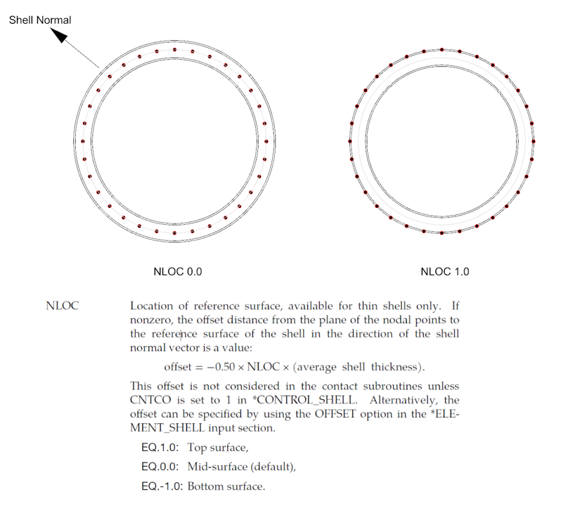
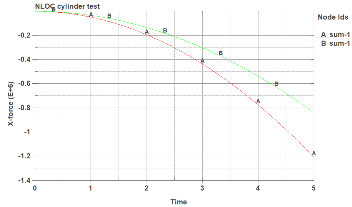
SubscriberThank you Jim. I have created a simple cylinder model in bending, with a single set of elements around the surface of the cylincer as shown in my figure above (not a DOUBLE layer of elements as I rarely do that). I impose a set of displacements at the midspan of the cylinder. I then ran the analysis in EXPLICIT with NLOC = 0 and NLOC = 1. The results confirm a different flexural stiffness im the two analyses, so I believe that NLOC is working as intended.
The curve A represents NLOC = 0. The curve B represents NLOC = 1. Because the element normals are pointing "out" from the central axis of the cylinder, the effect of NLOC 1 is to move the shell elements inward by one-half the shell thickness, thus reducing the moment of intertia of the cylinder.
-
March 6, 2024 at 5:09 pm
Jim Day
Ansys EmployeeRussell, in your prior post, you wrote the NLOC did not affect the flexural stiffness. Now you say that it does. Which is it?
Do the mass properties reported in d3hsp affected by NLOC? My recollection is that those properties are unaffected.
-
March 6, 2024 at 10:39 pm
Russell Gentry
SubscriberI ran two experiments. In the first experiment (see the first diagram in this thread), the results were non-sensical and NLOC did not appear to be working. In the second experiment, reported on above, NLOC does apppear to impact flexural stiffness of the cylindrical specimen. But I have not checked element stiffnesses, etc. It would be worth an in-depth analysis of the two cases to see which is the case. Right now I don't have the time to complete these, but happy to share my DYN files if you want to dig into it. Maybe this summer I will dig into and write a little white paper.
-
-
March 6, 2024 at 11:16 pm
Jim Day
Ansys EmployeeIn the first diagram (straight sandwich core), the value of NLOC doesn’t change the fact that the applied loads are at the node points. When NLOC is nonzero, the cross-section center is offset from nodes so it would seem reasonable that the section is no longer in pure tension. On the other hand, if the load were transverse to the straight member so as to produce flexure, it would make sense to me if NLOC had no effect.
Having the input data would be helpful in addressing this matter more thoroughly, but we cannot accept input files via the forum. You may share files if you submit a support case to https://customer.ansys.com and assign the task to “NA Structures”. If you choose to do that, please run both of your experiments using the explicit solver and again using the implicit solver, and note any differences in the effect of NLOC using these two solvers. Thanks!
-
- The topic ‘Mat 54 Laminates and NLOC in *PART_COMPOSITE_LONG’ is closed to new replies.


-
4678
-
1565
-
1386
-
1242
-
1021

© 2025 Copyright ANSYS, Inc. All rights reserved.


