

TAGGED: lumped-port, microstrip
-
-
March 28, 2022 at 4:46 pm
nvl
SubscriberMarch 28, 2022 at 5:23 pmPraneeth
Bbp_moderator
Kindly use "image" option to embed the screen shot into the post.
The said error may arise when one of the conductors connected to a lumped is touching/shorted with other metal.
Thus the port is only seeing one conductor instead of two conductors. This might not be your intention.
Please check for the intersection point and modify it accordingly.
This may sometimes happen if you have not explicitly added any air region which is required for your model. Please check.
All the very best Praneeth.
March 29, 2022 at 10:59 amSubscriberI tried to insert small copper box above the port and mark it as another conductor (reference), but now it replies
[error] Port '2': The port has no terminals defined on it. (12:44:18 PMMar 29, 2022)
[error] Simulation completed with execution error on server: Local Machine. (12:44:19 PMMar 29, 2022)
Trying to insert terminal to the port, it conflicts with existing port. Trying to insert terminal elsewhere, the terminal is not in port.
Possibly I don't have two conductors, as my circuit starts from the port and ends to copper plates that should produce RF waves.
April 4, 2022 at 2:10 pmSubscriberAnother problem, maybe linked to previous one.
I have done the simulation now, using wave port instead. Resulting current densities (used in phase determination in lines) are order of femtoamperes per square meter. There are no visible vectors anywhere. Maybe there is some problem with current transfer (should not be)?
I have tried to embed and re-embed the port, change port impedance, integration line, applied radiation etc.
April 4, 2022 at 2:57 pmBbp_moderator
Please share snapshots of your simulation model to help us serve you better as Ansys personnel cannot access the attachments in the forum.
All the very best Praneeth.
April 5, 2022 at 11:45 amSubscriberThe geometry with wave port is shown below.
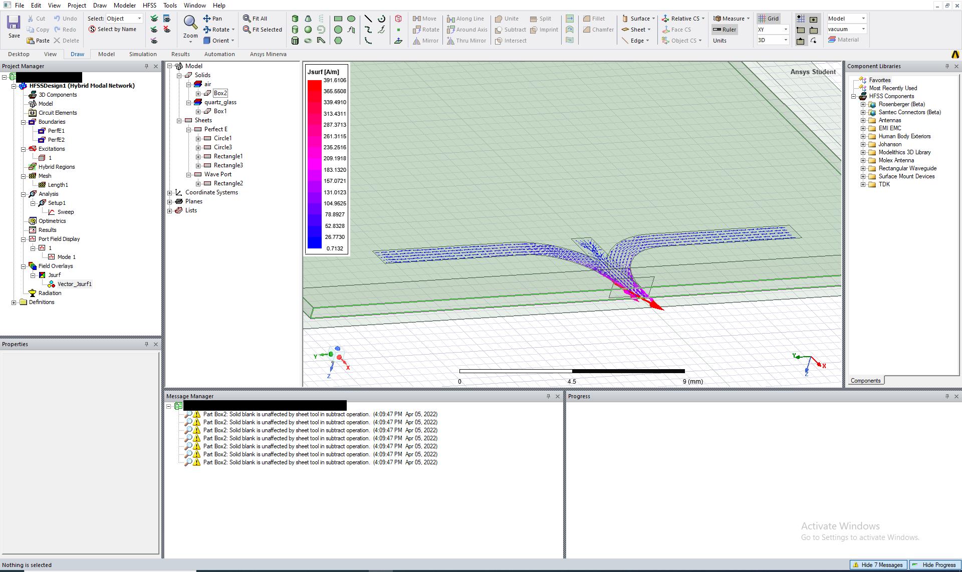
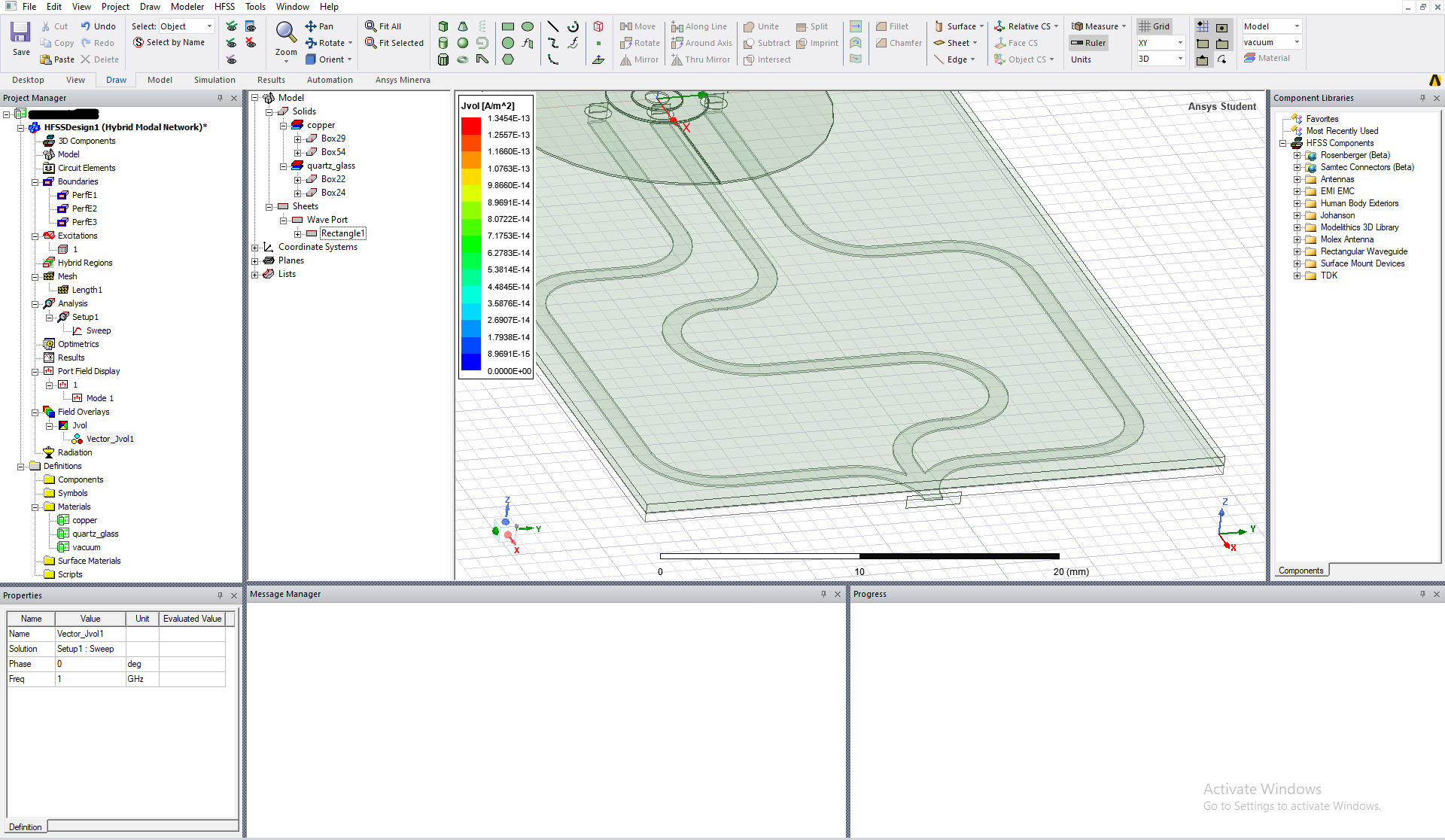 With planar lines and more simple geometry, I finally got believable current densities. I still wonder why current is so concentrated to the port?
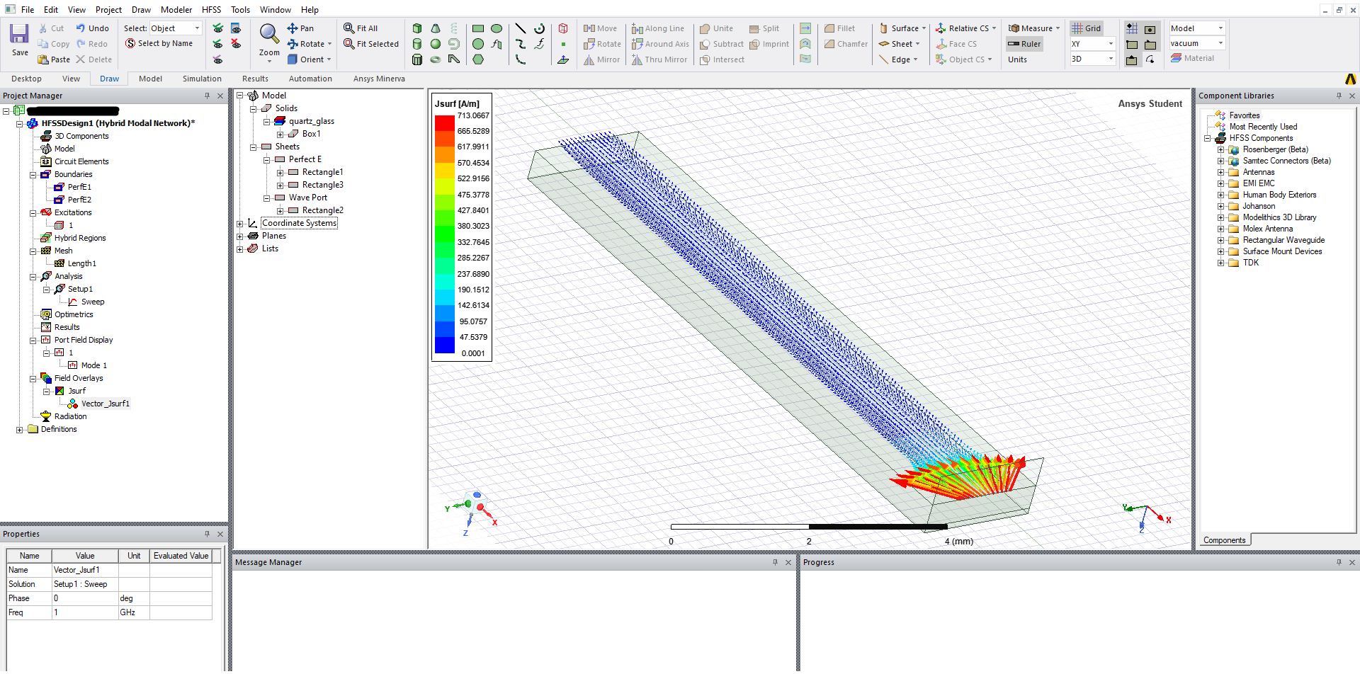 Even with this, it is difficult to see phase shift elsewhere.
April 5, 2022 at 12:47 pmBbp_moderator
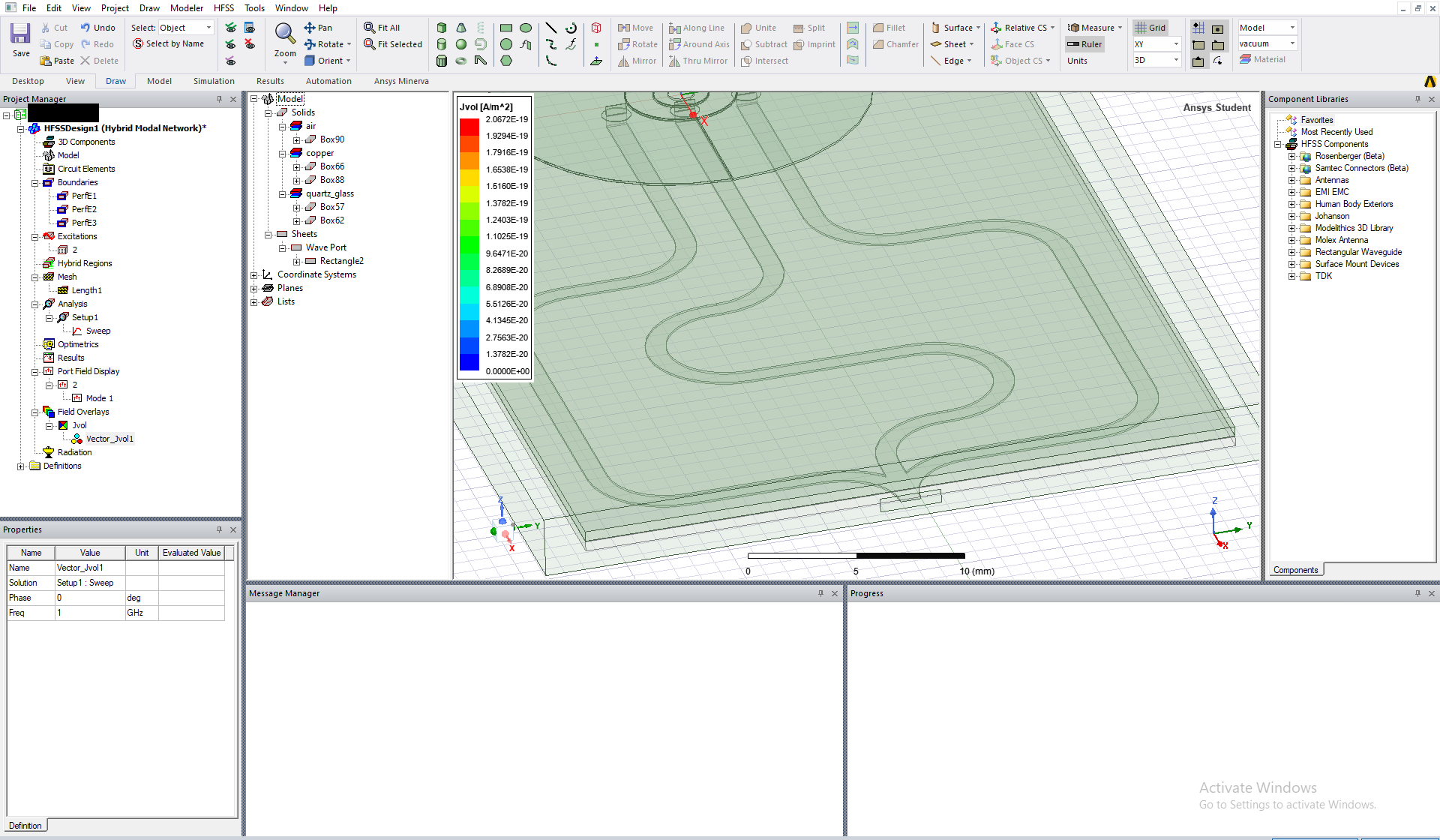
I do not see any air region defined in the model tree window. Are you using any auto open region in your model?
Please note that the default material in Ansys HFSS is PEC. It means that HFSS fills PEC automatically in the surrounding areas of your model.
You need to define air region explicitly surrounding your model.
Kindly check if this is applicable to your model.
All the very best Praneeth.
April 5, 2022 at 2:22 pmSubscriberNow I have inserted the air. The effect was that current density still decreased.
 I did same for planar one and it seems to work as I would like.
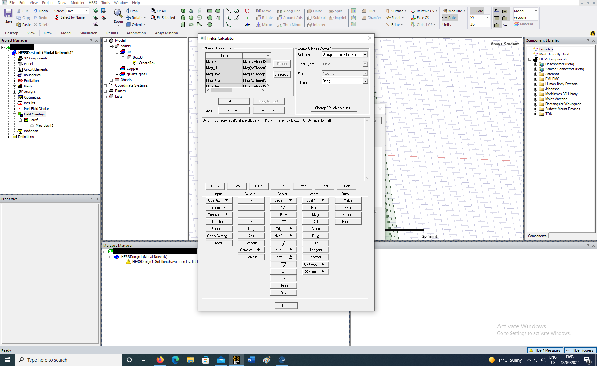
April 12, 2022 at 12:09 pmSubscriberI finally made it as partly planar model and calculated electric field in the charged plates successfully. Now I would like to calculate z-component of the electric field. Fields calculator guide advises to use Output -> Plot, but I don't have such setting. When I try to value/evaluate field normal to xy-plane, the response is: "The stack contents are incompatible with the current operation".
Viewing 8 reply threads- The topic ‘Lumped port for microstrip circuit’ is closed to new replies.
Ansys Innovation Space Trending discussions
 Top Contributors
-
peteroznewman
 3772
3772 -
scabo
 1358
1358 -
Dennis Chen
 1173
1173 -
javat33489
 1090
1090 -
Shyam Prasad V Atri
1014
Top Rated Tags
© 2025 Copyright ANSYS, Inc. All rights reserved.
Ansys does not support the usage of unauthorized Ansys software. Please visit www.ansys.com to obtain an official distribution.
-


The Ansys Learning Forum is a public forum. You are prohibited from providing (i) information that is confidential to You, your employer, or any third party, (ii) Personal Data or individually identifiable health information, (iii) any information that is U.S. Government Classified, Controlled Unclassified Information, International Traffic in Arms Regulators (ITAR) or Export Administration Regulators (EAR) controlled or otherwise have been determined by the United States Government or by a foreign government to require protection against unauthorized disclosure for reasons of national security, or (iv) topics or information restricted by the People's Republic of China data protection and privacy laws.


