老师您好,目前我正在参照官网案例“CWDM_splitter_1310_4ch_2D_TE_topology”进行光子器件的逆向设计工作,目前遇到了一个问题,还请老师解答一下:
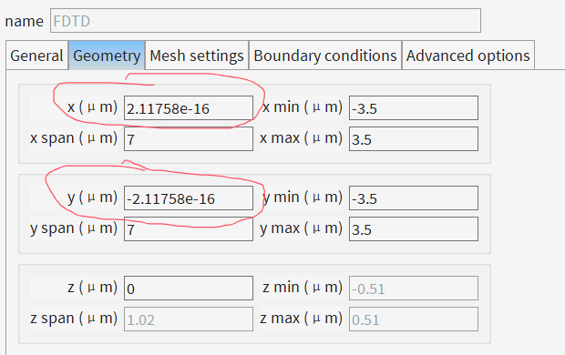
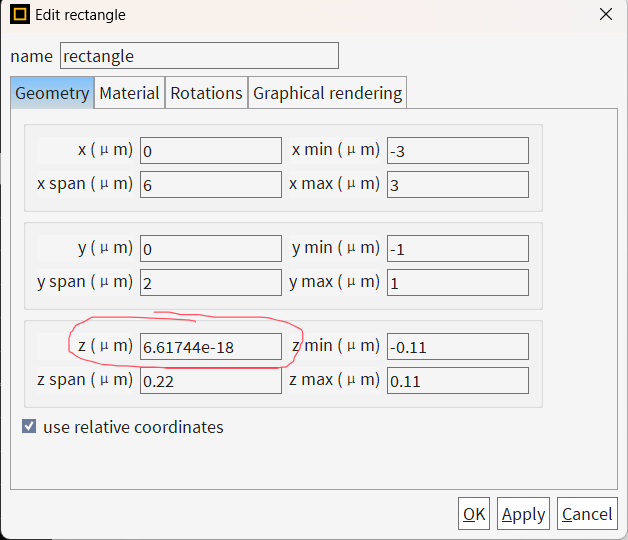
官网案例给的是2D仿真,我所进行的是3D仿真。再进行base_simulation建模时,我是完全参考案例中的设置进行的,即在设置fom监视器时,会在相应位置处设置一个mesh,mesh的跨度刚好为2个dx。但是我在运行仿真时,会出现警告:“WARNING: The monitor "fom_1" is not aligned with the grid. Its distance to the nearest mesh point is [2.00000159e-07]. This can introduce small phase errors which sometimes result in inaccurate gradients.”。我也已经检查了所设置监视器的位置和mesh的位置,发现没有问题,监视器的位置刚好处于mesh的中心。
不清楚究竟是什么原因造成的,还请老师予以解答。下面是我所写的脚本。祝您身体健康,工作顺利!
switchtolayout;
selectall;
delete;
## SIM PARAMS
L_block=6e-6;
H_block=6e-6;
num_of_outport=4;
num_of_input=num_of_outport;
with_of_input=2.0e-6;
length_input=5e-6;
length_output=5e-6;
h_si=220e-9;
inputmode=[1,2,3,4];
opt_size_x=L_block;
opt_size_y=H_block;
opt_size_z=h_si;
size_x=opt_size_x+1e-6;
size_y=opt_size_y+1e-6;
size_z=2e-6;
with_of_output=0.5e-6;
gap_of_outport=H_block/num_of_outport;
wg_index = 3.48;
bg_index = 1.44;
dx = 20e-9;
addfdtd; ##
set("dimension",2); # 1 = 2D, 2 = 3D
set("x",0);
set("x span",size_x);
set("y",0);
set("y span",size_y);
set("z",0);
set("z span",size_z);
set("mesh accuracy",3);
set("simulation time",4000e-15);
set("index",bg_index);
set("auto shutoff min",1e-7);
addrect; ##
set("name","input");
set("x max", -L_block/2);
set("x min", -L_block/2-length_input);
set("y min", -H_block/2);
set("y max",-H_block/2+with_of_input);
set("z", 0);
set("z span", h_si);
set("index",wg_index);
for (index=linspace(-(num_of_outport-1)/2,(num_of_outport-1)/2,num_of_outport)){
addrect; ##
set("index",wg_index);
#set("material","Si (Silicon) - Palik");
set("z", 0);
set("z span", h_si);
set("x min", L_block/2);
set("x max", L_block/2+length_output);
set("y", index*gap_of_outport);
set("y span",with_of_output);
}
addmode;##
set("name","source");
set("direction","Forward");
set("injection axis", "x-axis");
set("x", -size_x/2+0.2e-6);
set("z",0);
set("z span",2e-6);
set("y", -H_block/2+with_of_input/2);
set("y span",5e-6);
set("wavelength start",1.55e-6); ##
set("wavelength stop",1.55e-6);
updatesourcemode(1);
addpower;#
set("name","opt_fields");
set('monitor type','3D'); # 1 = point, 2 = linear x, 3 = linear y, 4 = linear z, 5 = 2D x-normal, 6 = 2D y-normal, 7 = 2D z-normal, 8 = 3D
set("z",0);
set("z span",opt_size_z);
set("x", 0);
set("x span",opt_size_x);
set("y", 0);
set("y span",opt_size_y);
index=linspace(-(num_of_outport-1)/2,(num_of_outport-1)/2,num_of_outport);
for (xnum=1:num_of_outport){
addpower;
set("name","fom_"+num2str(xnum));
set("monitor type",5); # 1 = point, 2 = linear x, 3 = linear y, 4 = linear z, 5 = 2D x-normal, 6 = 2D y-normal, 7 = 2D z-normal, 8 = 3D
set("x", size_x/2-0.2e-6);
set("z",0);
set("z span",2e-6);
set("y", index(xnum)*gap_of_outport);
set("y span",1.5e-6);
if(1){
addmodeexpansion;##
set("name","mode_expansion"+num2str(xnum));
set("monitor type",1); # 1 = 2D x-normal, 2 = 2D y-normal
set("x", size_x/2-0.2e-6);
set("z",0);
set("z span",2e-6);
set("y", index(xnum)*gap_of_outport);
set("y span",1.5e-6);
select("mode_expansion"+num2str(xnum));
setexpansion("input", "fom_"+num2str(xnum));
set("mode selection","user select"); # use the 'user select' option
seteigensolver("use max index",1); # specify a custom value for 'n'
updatemodes(1);
}
addmesh; ##
set("name","fom_"+num2str(xnum)+"_mesh");
set("set maximum mesh step",1);
set("override x mesh",1);
set("dx",dx);
set("override y mesh",0);
set("override z mesh",0);
set("x",size_x/2-0.2e-6);
set("x span",2*dx);
set("y",index(xnum)*gap_of_outport);
set("y span",1.5e-6);
set("z",0);
set("z span",size_z);
}
## For visualization later
addindex;
set('name','global_index');
set('x min',-size_x/2);
set('x max',size_x/2);
set('y min',-size_y/2);
set('y max',size_y/2);
set('z min',-size_z/2);
set('z max',size_z/2);
set('enabled',false);
## Optional: Naive design which can be used as initial guess
index=linspace(-(num_of_outport-1)/2,(num_of_outport-1)/2,num_of_outport);
addstructuregroup;
set("name","initial_guess");
for( i=1:num_of_outport ) {
addwaveguide;
set("name","bend"+num2str(i));
set("base width",500e-9);
set("base height",220e-9);
set("base angle",90);
poles = [-opt_size_x/2,-H_block/2+with_of_input-i*with_of_input/4+with_of_input/8;
0,-H_block/2+with_of_input-i*with_of_input/4+with_of_input/8;
0,index(num_of_outport-(i-1))*gap_of_outport;
opt_size_x/2,index(num_of_outport-(i-1))*gap_of_outport];
set("poles",poles);
set("index",wg_index);
addtogroup("initial_guess");
}