Ansys Assistant will be unavailable on the Learning Forum starting January 30. An upgraded version is coming soon. We apologize for any inconvenience and appreciate your patience. Stay tuned for updates.
LS Dyna

LS Dyna

Topics related to LS-DYNA, Autodyn, Explicit STR and more.

LS-DYNA FSI Aortic Valve

    • J.H.L.B.Geurts
      Subscriber

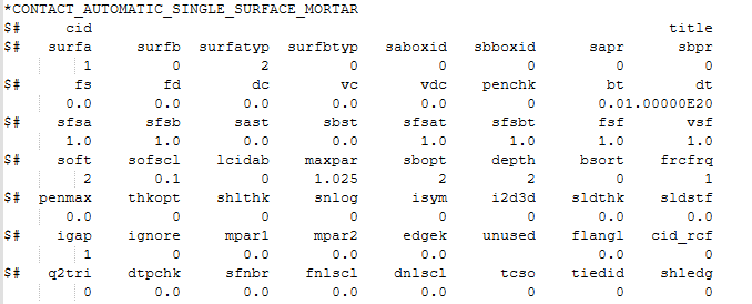
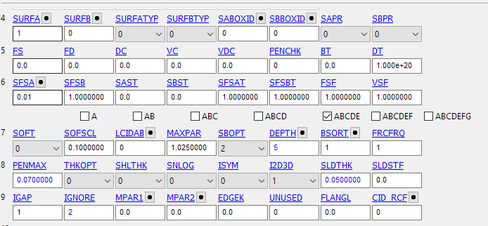
      I am in the process of building a strongly coupled implicit FSI (with ICFD) model of an aortic valve, studying the effect of fibre orientation using the MAT_295 HGO model. I believe this material model requires me to use solid leaflets, as shells are not supported (yet). This makes it more difficult, though. When the solid leaflets touch, the fluid surface mesh follows and touches as well, which leads to penetration of the fluid mesh. With shells, this is not an issue, since the shell thickness ensures that there is an offset, ensuring that the fluid surface meshes do not touch. I tried many things, like SLDTHK of 0.1/0.25 mm (solid leaflets thickness being 0.25 mm), but this would easily lead to a blow-up due to the contact. This is the current contact keyword card:


      Does anyone have an idea I could try? Thanks a lot in advance!!

    • Nils Karajan
      Ansys Employee

      Hey there, yes, it's a bummer that MAT_295 is not yet available for shells. Often times I just use *MAT_SOFT_TISSUE for the leaflets, as it allows you to define one family of fibers and it also works with shells. 

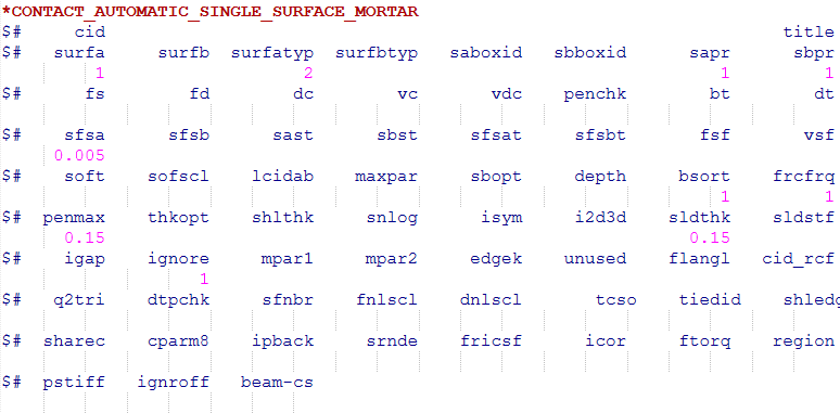
      Regarding your approach with solid elements, I assume you have one element across the leaflet thickness. If so, you could try the following:


      Herein, I usually try to set "sfsa" as low as possible, which will help to prevent the simulation from blowing up. The current value of 0.005 worked fine for a solid leaflet in my case. The other two parameters "penmax" and "sldthck" I usually set to roughle half the element size. So if your deck is in "mm" lengthscale, then the given values of 0.15 shoud work. For shell leaflets, I would use the same logic but set sldthck=0.

      If you still don't get this to work, you can try to cover the surface of the leaflet with null shells, i.e., these are shells with no stiffness using *MAT_NULL and very small density. Then you can reference them in the contact definition. 

      Another thing to remember is to set a reasonable time step. For leaflet FSI, we usually use 0.0002 seconds. 

      Hope this helps.


      • J.H.L.B.Geurts
        Subscriber

        Hello Nils,

        Thank you for your reply! Unfortunately, my material model requires 2 fiber families and is anisotropic, so I cannot use the MAT_SOFT_TISSUE. It was advised for me to use at least 3 elements across the thickness, so I did. This means that the elements are 0.0833 mm because of the total thickness of 0.25 mm. My surface element size is 0.35 mm. Would this penmax and sldthk then be half the element size of an element through the thickness, say 0.05 mm? 

        Also, I am encountering another problem: the leaflets seem to resist bending a lot, because of shear-locking. Unfortunately, MAT_295 is very restricted in what element formulations are supported. Elform 2 seems to be my only option that works somewhat, but I believe it is shear-locking a lot. Do you potentially know a way around this? I do not think there is a different elform to use, since elform 1 seems to be way worse, even with hourglass type 6. Maybe more segments through thickness? 

        Thank you so much in advance!! I will try your recommendation of the penmax, sldthk and sfsa values.

    • J.H.L.B.Geurts
      Subscriber

      Hello Nils,

      Thank you for your reply! Unfortunately, my material model requires 2 fiber families and is anisotropic, so I cannot use the MAT_SOFT_TISSUE. It was advised for me to use at least 3 elements across the thickness, so I did. This means that the elements are 0.0833 mm because of the total thickness of 0.25 mm. My surface element size is 0.35 mm. Would this penmax and sldthk then be half the element size of an element through the thickness, say 0.05 mm? 

      Also, I am encountering another problem: the leaflets seem to resist bending a lot, because of shear-locking. Unfortunately, MAT_295 is very restricted in what element formulations are supported. Elform 2 seems to be my only option that works somewhat, but I believe it is shear-locking a lot. Do you potentially know a way around this? I do not think there is a different elform to use, since elform 1 seems to be way worse, even with hourglass type 6. Maybe more segments through thickness? 

      Thank you so much in advance! I will try your recommendation of the penmax, sldthk and sfsa values.

    • Nils Karajan
      Ansys Employee


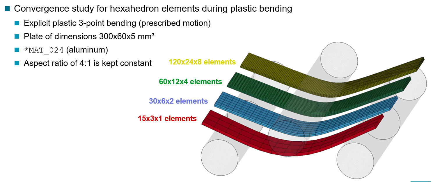
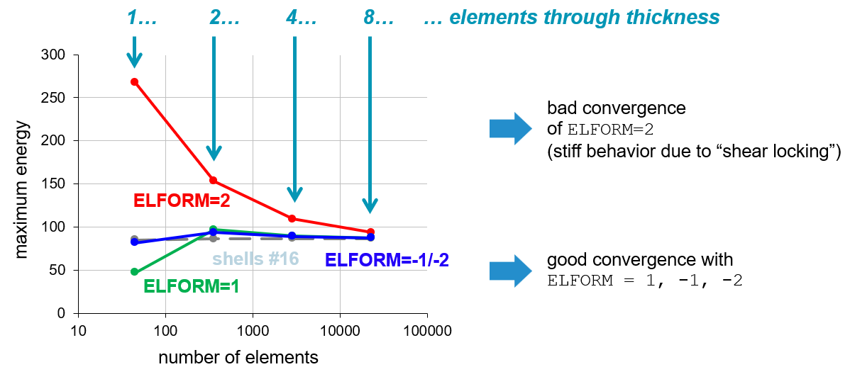
      If you need two families of fibers then MAT_295 will be the one and you need to model it using solid elements. To see how many elements you will need across the thickness can be revealed with a convergence study. A colleague of mine did this some years back and concluded that three would be perfect but two elements across will reach an accuracy that is better compared to the general uncertainty in bio materials. 


      Of course you will not have this behaviour when using elfrom=2, as these elements suffer from locking during bending when used in a bad aspect ratio. This is why elform=-1/-2 were introduced, where elform=-1 is my goto element while elform=-2 can sometimes improve results and convergence in very tough situations.

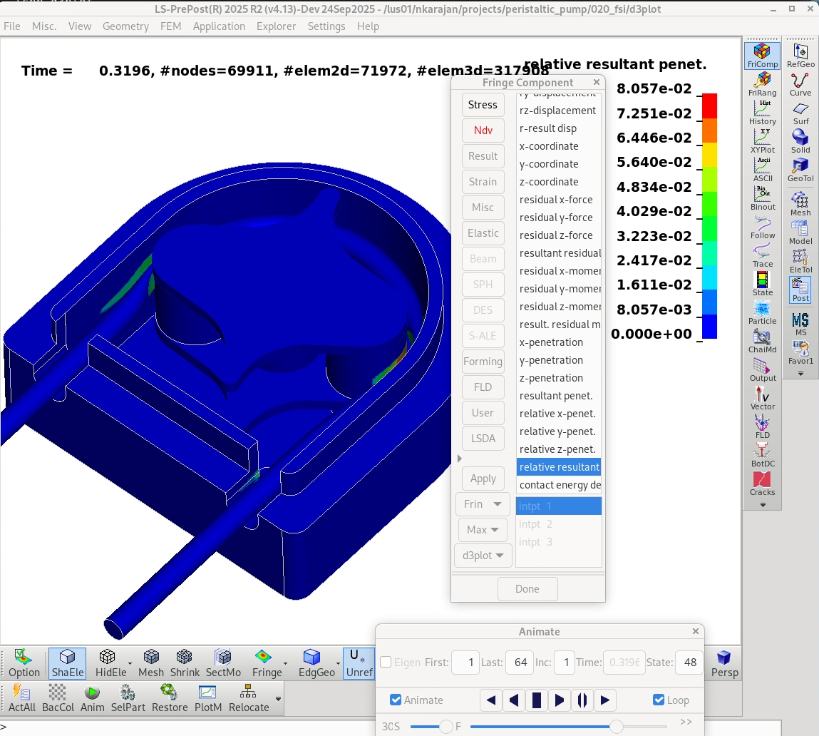
      You need to experiment to obtain the optimal value for penmax but I would say penmax=0.07mm and sldthk=0.05 mm is a good starting point as well as sfsa=0.01. Please monitor the penetration through your simulation by setting penout=2 in *CONTROL_OUTPUT to be able to fringe relative penetration in the d3plot files. I usualy aim for a utilization window of ~20-60% penetration of the contact thickness. If you only penetrate 10% of penmax, then your contact is mostlikely too stiff and you can tune it down with sfsa and vice versa, you don’t want to come too close to 100%.


      • J.H.L.B.Geurts
        Subscriber

        Hi Nils,

        Thank you for your suggestions, I have tried them. It seems that it does not show the relative penetration in the d3plot file, with the penout=2 option enabled. I assumed to fringe the penetration using Fringe component > Ndv > relative pen. But, it does not show anything for me. I am trying both soft = 0 and 2, but with no success. Have I forgotten something? These are my current contact keyword cards:

    • Nils Karajan
      Ansys Employee


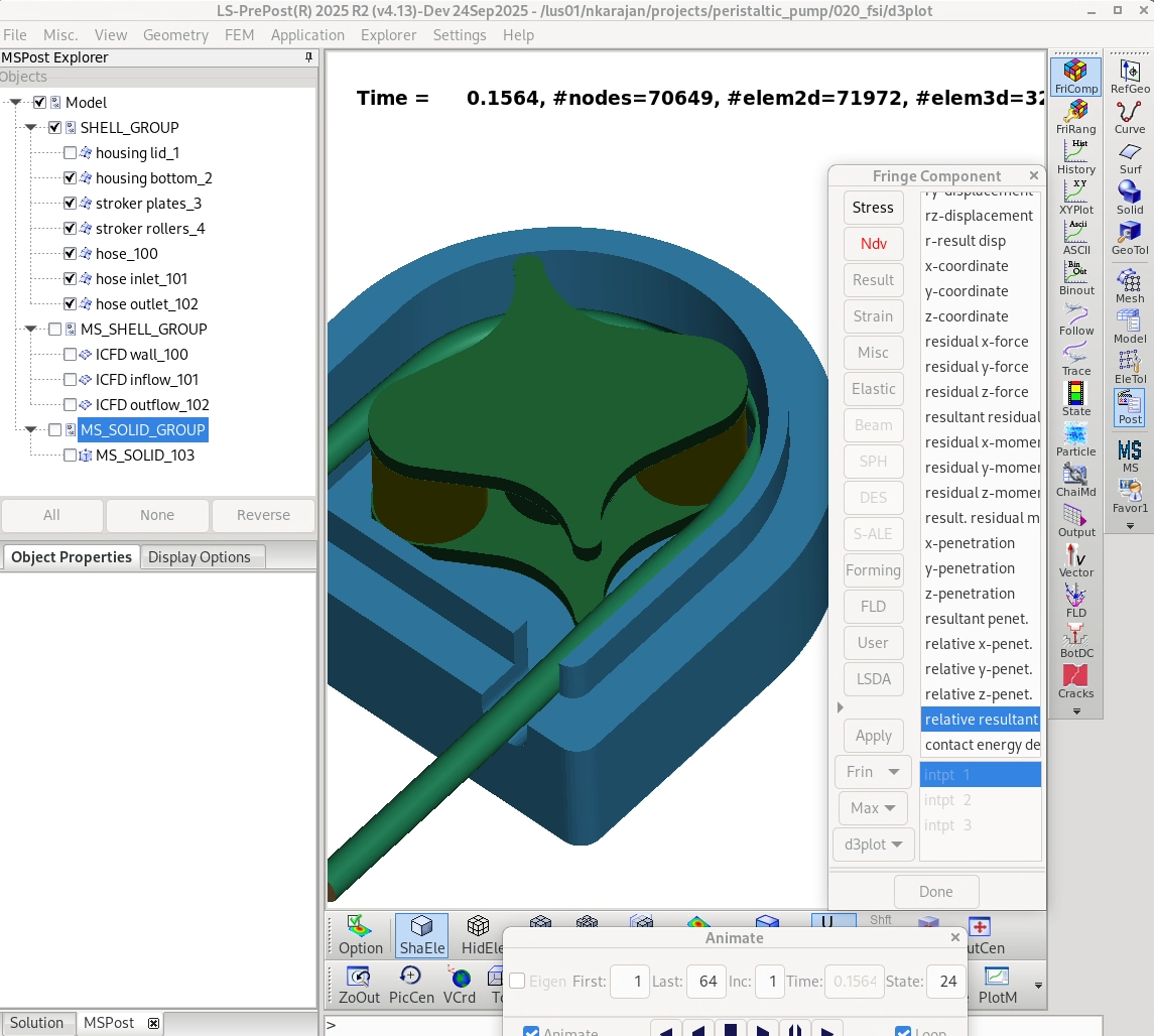
      I assume you are using the MORTAR option in your contact definition? If so, then SOFT does not have a meaning and penout=2 should provide the relative penetration in the d3plot (like you said under fringe component/ndv/relative penetration). And then you should also use a recent version of LS-PrePost.

      An interesting thing I just noticed though is when the d3plot files contain ICFD data. Then by default the multiphysics “solution explorer” on the left hand side is opened and it appears that the “solution explorer” breaks the functionality of the “Fringe Component” feature for structural mechanics. I could successfully reproduce your behavior, where I’m able to select the relative penetration but it does not show up. 


      You can fix this though by closing the “Solution Explorer” on the left, which will instantly fringe the relative penetration depth.


      • J.H.L.B.Geurts
        Subscriber

        Hi Nils,

        Yes, I am using the MORTAR option. Thanks for mentioning the fix to fringe out the relative penetration. This indeed fixes it! The penetration is quite high with the current SFSA, so I will now fine-tune to achieve a penetration within the window of 20% to 60% of the SLDTHK of 0.05mm. 

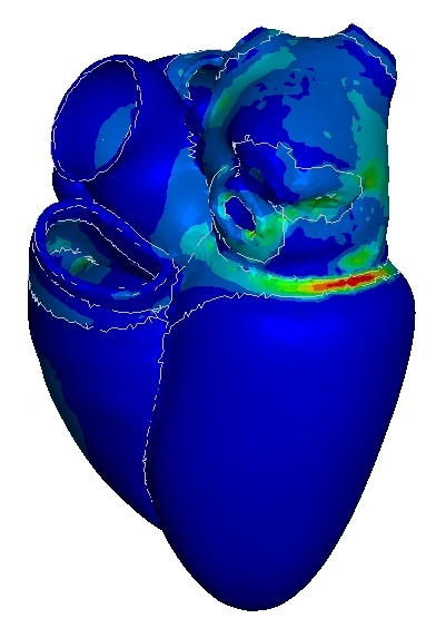
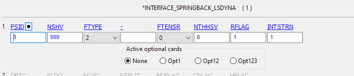
        If you do not mind and have got the time, I have got a different issue for which I do not know the answer to. Since I am also including pre-stretch of the tissue with interface_springback, I have encountered a few issues. In the follow-up simulation, the stress and strains are not being saved; it reset to 0. I have tried incorporating the reference geometry with INITIAL_FOAM_REFERENCE_GEOMETRY, and initializing all the history variables, but with no success. I have tried the same setup with an isotropic hyperelastic material, MAT 77, which does work. Do you know by any chance if it's even possible to use springback with MAT 295? If not, maybe there is a way around this to make it still work? I have included a picture of the current springback setup, which will output INITIAL_STRESS_SOLID, INITIAL_STRAIN_SOLID, and REFERENCE_GEOMETRY (which I later convert to initial foam).

        I really greatly appreciate the help!
    • Nils Karajan
      Ansys Employee

      I'm glad this helped! 

      Regarding the pre-stress, I think you do everything correctly. The only difference is that I usually use ftype=10. What version of LS-DYNA are yoiu using? With R16.0.0, I was able to start with this pre-stress in MAT_295:


      There were some changes in the way how the dynainfile is produced and it now includes the deformation gradient such that hyper-elastic materials initialize correctly. Earlier releases of LS-DYNA did not have this and the dynain files from earlier releases can't be initialized with R16.0.0

Viewing 5 reply threads
  • You must be logged in to reply to this topic.
[bingo_chatbox]