-
-
April 30, 2024 at 9:53 am
anjaliar
SubscriberI have been trying to optimize bend radius for silicon waveguide of 6 um width. The expected radius for low loss is around 13-15 mm. For values above say, 500 um, the results are coming wrong. Does it have anything to do with memory requirements? We use a system with 64 GB RAM.
Thanks in advance.
-
April 30, 2024 at 8:01 pm
Guilin Sun
Ansys EmployeeIt is hard to tell what is wrong. Could you please post some settings and result? give as many details as possible, Please.
Â
-
May 7, 2024 at 11:26 am
anjaliar
Subscriber
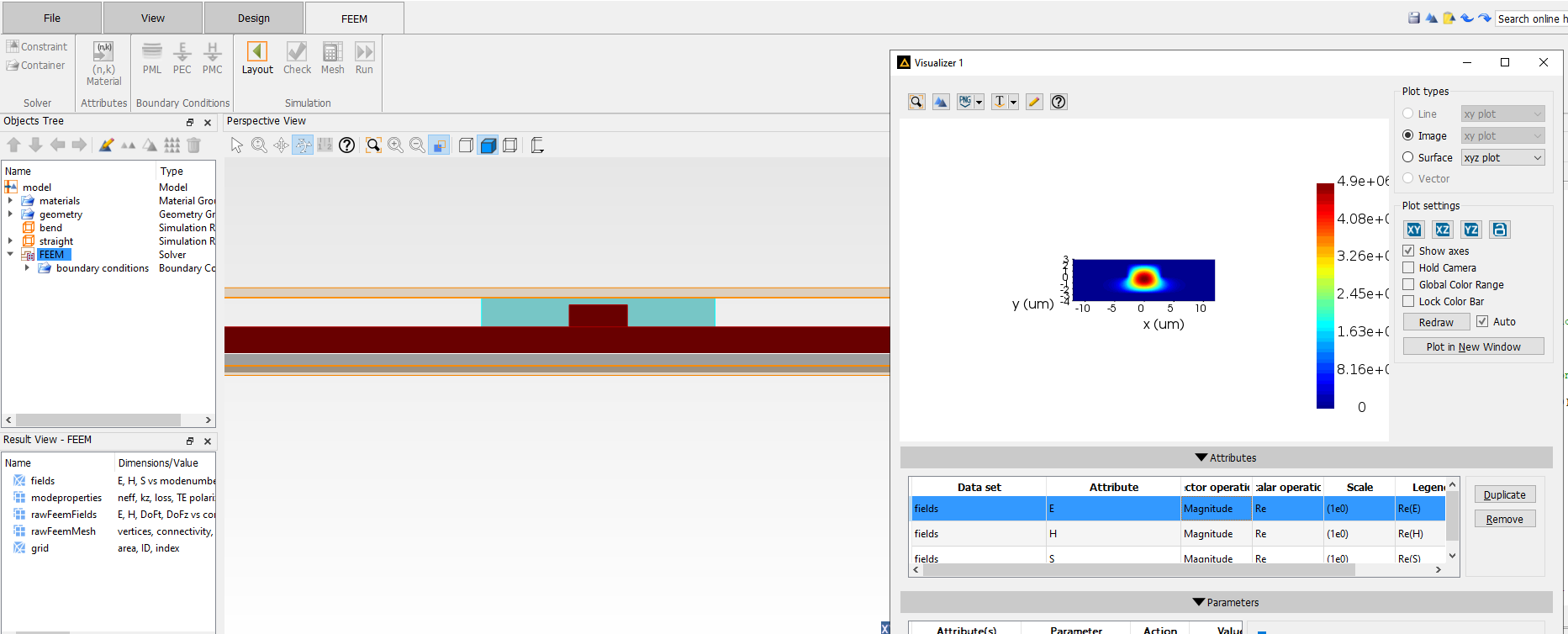
The structure simulated is a silicon rib waveguide. The mode 1 field (for straight waveguide) is shown along with the structure.
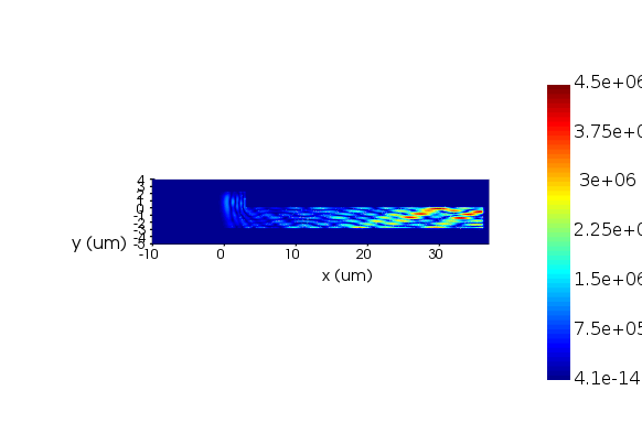
Bend waveguide simulation for a bent radius of 20 um is done. The field obtained is as below (for mode 1).
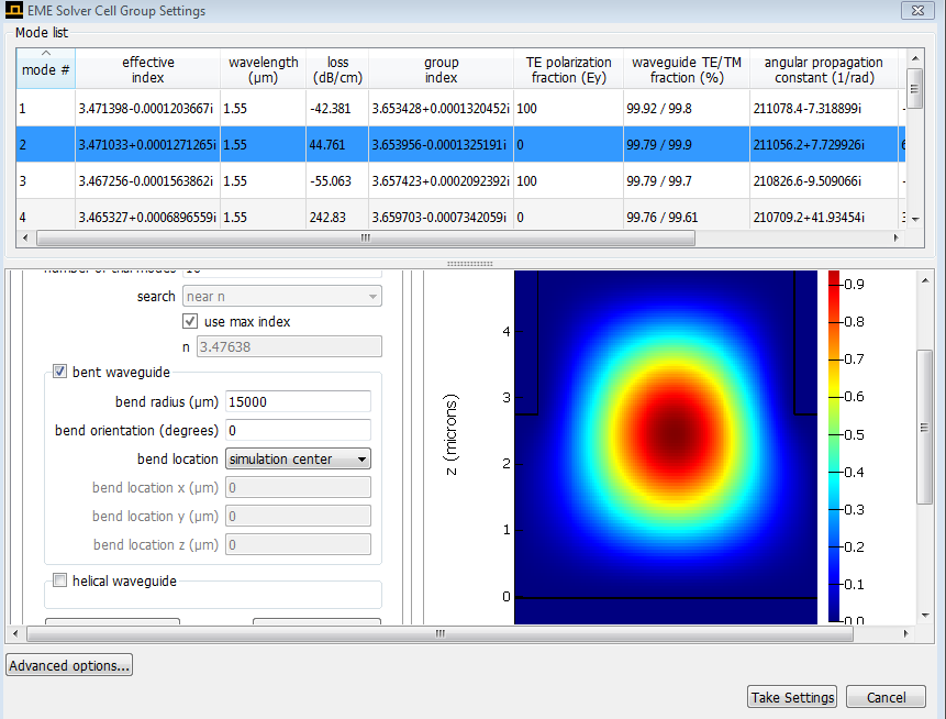
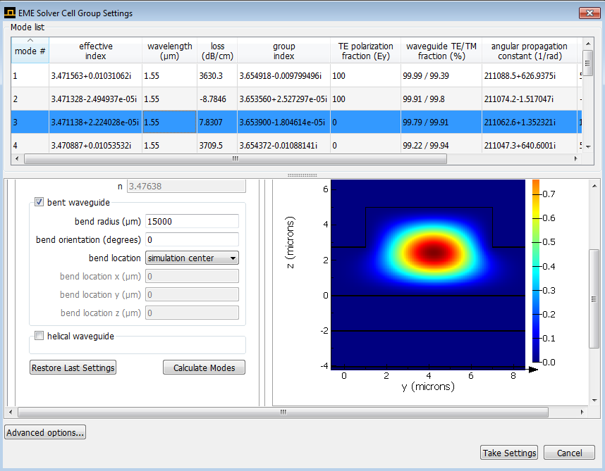
The substrate and slab x-span and z-span are taken as 40,000 um. The waveguide length is 40,000 um and is centered at x=0. The bend simulation region span was changed to xmin=-10 um to xmax= 36 um. Apart from xmin, remaining has a shell boundary condition, with shel thickess of 1 um. Bend location in FEEM is fixed as (0,0,0). Edges per wavelength = 5, and polynomial order = 4. No. of modes chosen are 2. Auto remove pml modes has been activated.
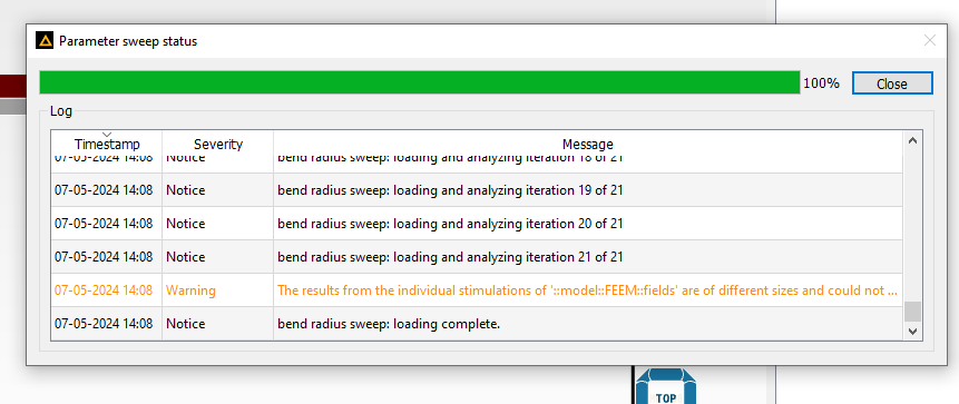
The bend radius is swept from 12,000 to 18,000 um. Both "mode properties" and "fields" are monitored.Â
1) One issue is the warning which says the fields returned are of different sizes.
Â
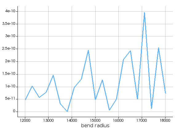
2) The loss vs. bend radius plot obtained is shown below. I expect a gradual decrease in loss with increase in radius, which is not the case here.
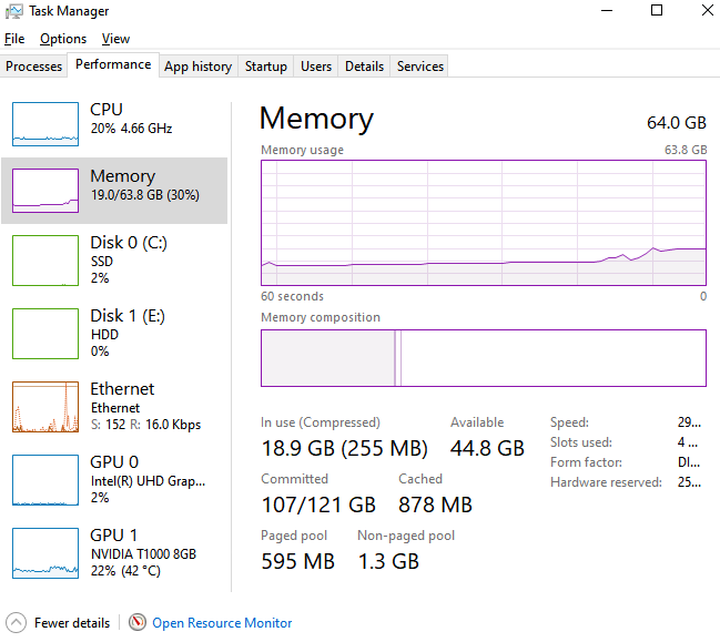
3) The system used is of 64 GB RAM. I had monitored the memory usage during the simulation. Attached is the screenshot at an instance.
Please suggest what might be wrong here.
Thank you.
Â
-
May 7, 2024 at 4:04 pm
Guilin Sun
Ansys EmployeeIf the mode profile becomes like this:
I am not sure if you still can call it as a mode.
Maybe such waveguide cannot be bent to small radius.
Q 1) One issue is the warning which says the fields returned are of different sizes.
This issue arises when the mesh changes size. Please try fixed override mesh size. Maybe FEEM needs a feature to lock the mesh.
Q The loss vs. bend radius plot obtained is shown below. I expect a gradual decrease in loss with increase in radius, which is not the case here.
The loss is too small. Please use larger simulation region. The loss might be mostly from PML.
Memory: it might mean you have used much finer mesh. You may try to use higher order.
Â
-
May 22, 2024 at 7:17 am
anjaliar
SubscriberHi Guilin,
 The problem I was facing has been resolved. It seems I did not have to increase the bent simulation region too much. Inorder to check the fields, I had to check for individual parameter values instead of giving a sweep.
1) I noticed that the mode number keeps changing for a particular mode (for different bent radius). So, the plot obtained while sweeping the parameter contains loss values of different modes (not necessarily the mode of interest).
2) I tried 'lock mesh' option available in FEEM. It prevented the sweep from running successfully.
3) I used larger value in 'polynomial order' in mesh settings, and checked the meshing. It did not result in any change whichever value I chose.
I would also like to bring to your notice that in the example of bent waveguide in FEEM (https://optics.ansys.com/hc/en-us/articles/4409707153811-Bent-Waveguide-FEEM), the script "waveguide_bend_sweep.lsf" displays results in dB/cm (while the values are in SI unit).
Thank you.
Â
-
May 22, 2024 at 7:43 am
anjaliar
SubscriberIn relation to this, the mode field I am interested in looks like this (for 15 mm bend radius). The entire field seems to have shifted to the slab.
Also, I have followed the instruction in this post (/forum/forums/topic/is-it-possible-to-simulate-bent-waveguide-using-eme/) to check the bending loss using EME as well. I found that the loss for the same bend radius keeping varying with change in span of simulation region.Â
The bending loss for 15 mm bent radius, as obtained from FEEM was 50 dB/cm, whereas EME gives different values as shown (for same settings, but different simulation region span).
Here, 44.7 dB/cm is the value obtained, which has been reduced to 7.8 dB/cm for a larger simulation span.
How much span should I keep while performing EME simulation? Please suggest what can be done.
Thank you.
Â
-
- The topic ‘Loss vs. waveguide bend radius in Lumerical FEEM’ is closed to new replies.
- STEP File Exports
- Optic studio-zemax operand values are different from the plot (Genc and Denc)
- Assistance Needed for Wavelength Adjustment in Optical Ring Modulator Simulation
- Matlab linkage Zemax memory overflow problem
- Relay Lens Optimization
- Gaussian beam propagation and field by angle
- RMS Spot size in Non-Sequential Method in Zemax Opticstudio
- How to calculate Wavefront RMS when “Remove Tilt” is chosen in Wavefront Map?
- Issues opening Zemax files
- Zemax: creating an array of tilted source
-
2262
-
925
-
599
-
591
-
497
© 2025 Copyright ANSYS, Inc. All rights reserved.