-
-
September 23, 2024 at 6:13 pm
Sept
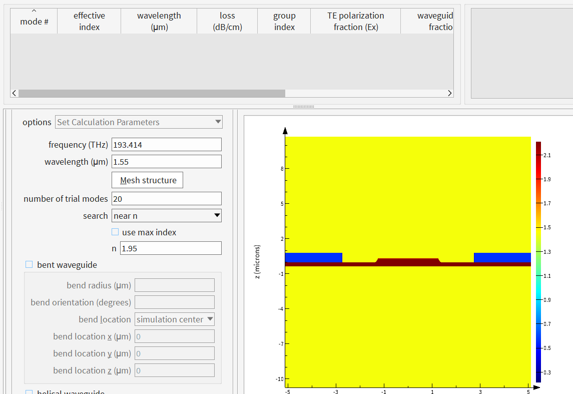
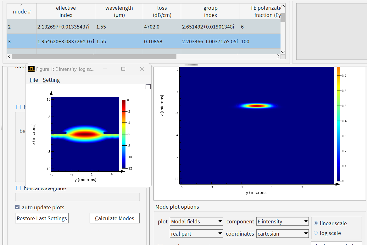
SubscriberGood Afternoon, I am trying to see if my current approach to calculating loss due to the placement of electrodes is correct. I am currently using PML boundaries and was wondering if I should be worried about how far they are placed. I have plotted the E field intensity in linear scale and log scale (see attached) just to show how far the field extends. Any help would be appreciated.
-
September 24, 2024 at 4:17 pm
Guilin Sun
Ansys EmployeeIt is a good practice to do convergence testing by gradually increasing simulation spans. Since mode profile has long tails which can penetrate into the metal electrodes, you may need insrease y span longger. Of course the tail may not be exactly zero. So you can set the colorbar to certain value, say 1e-8 or smaller (intensity, eg, the tail min intensity at the ymax), I believe the loss will not change any further in most cases. You can compare the result with two different y span and see how the loss changes.
-
- You must be logged in to reply to this topic.


-
3442
-
1057
-
1051
-
917
-
896

© 2025 Copyright ANSYS, Inc. All rights reserved.


