-
-
June 30, 2018 at 2:18 am
thanhttdt
SubscriberHi everyone,
I have a question that
1. How to set up these loads combination in Ansys workbench in 1 block (figure a) or 2 block (figure b)
2. How to apply pressure load in random position on the plate instead of split surface (I just see remote force, but no remote pressure)?
For example: there is a platform (figure 1)
Figure 1: Geometry topology of platform
Load included
· Load combination 1: Pallet lifter weight
· Load combination 2: Uniform distributed load (UDL)
This is an attached file: https://drive.google.com/drive/folders/1kQqVOflaKY1rz2i6v37YWUn829UW48aI?usp=sharing
Thanks for your kind support.
Best Regards,
-
July 1, 2018 at 1:34 am
Sandeep Medikonda
Ansys EmployeeHello thanhttdt,
In order to create a coupled analysis, you just need to drag one analysis system onto the other.
so for a figure a, drag and drop the geometry from the Component systems on the left-hand side of workbench project page and then drop a Static structural Analysis system onto it. Follow the same procedure for figure b as well where you can drag another Static structural analysis onto the Model cell.
Check out the thermal-structural analysis set up here:
https://www.youtube.com/watch?v=QhyAfzhChk0&list=PLQMtm0_chcLx4NoPbUFkqLHoOomntN0Gr&index=24
Regards,
Sandeep Medikonda
-
July 1, 2018 at 1:50 am
Sandeep Medikonda
Ansys EmployeeAlso, I don't quite follow the second part of your question.
It is my understanding that when you apply a Remote Force, it is equivalent to a regular force load on a face or a force load on an edge, plus some moment.
Now, pressure is a scalar, typically applied perpendicular to the face. So, you can create named selections in your model and apply pressure to those faces.
https://www.youtube.com/watch?v=ByVtViHQTMA
-
July 1, 2018 at 2:49 am
thanhttdt
SubscriberHi SandeepMedikonda,
So it means that if I want to apply pressure on the plate, I have to split this plate into some smaller pieces first and then apply pressure on these small items, is it right?
And there is no way to apply pressure on the random placed on the plate without splitting.
Is my understand true?
Thanks for kind help,
-
July 1, 2018 at 5:28 am
peteroznewman
SubscriberHi thanhttdt,
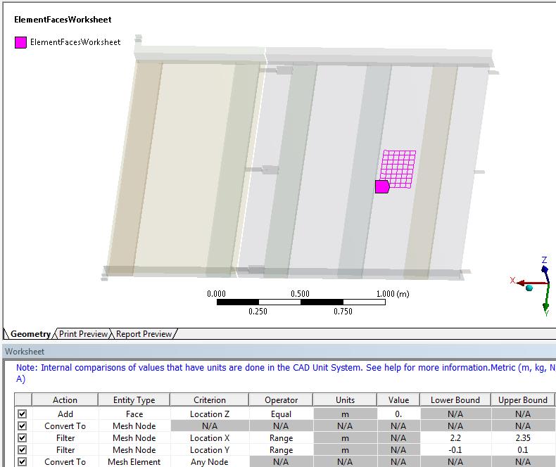
I created a named selection using the Worksheet option to select Element Faces within a range of X and Y coordinates as shown below.
However, when I tried to use that Named Selection in a Pressure, it wouldn't take it. I wonder if someone knows why.
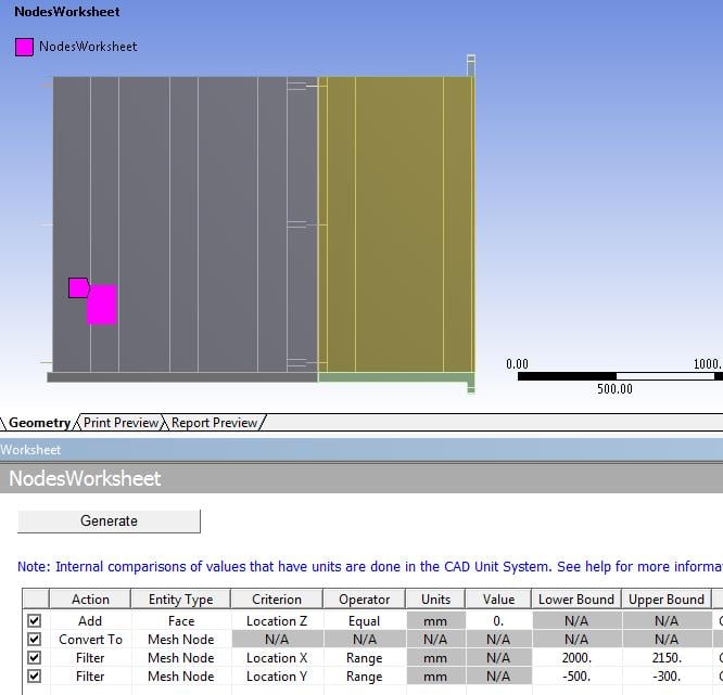
I also tried to make a Named Selection of Nodes, and couldn't get that to show up in a Force assignment either.
I was using ANSYS 18.2. What version are you using?
Best regards,
Peter
-
July 1, 2018 at 7:33 am
thanhttdt
Subscriber
Thanks for your kind support
I use Ansys 18.2 too
Would you mind to suggest me some solutions
Now I have to check vehicle tyre print pressure. So there are some position of tyre print need to be checked.
If I split the top plate, it seems unreasonable
Thanks in advance
-
July 1, 2018 at 8:33 am
thanhttdt
Subscriber
Did you get this situation?
But if I select a plate, I can apply pressure there
If I only select a group of element, same story with you happen, cannot apply pressure with this selection.
It's a bit confusing here
-
July 1, 2018 at 1:31 pm
peteroznewman
SubscriberHi thanhttdt,
I checked the ANSYS Help file and the entry for Force under the category of Topology, Nodes are supported, while the entry for Pressure under the category of Topology, there is no mention of element faces (I didn't expect nodes since pressure needs an area). I should put this in as an enhancement request, since you have a good example of why it would be useful.
I'm curious why, when I had a worksheet that selected nodes, I couldn't apply a force either, just like you saw for pressure. This should work and I hope someone can explain why it's not working.
If this was to work, you could convert the pressure to force since you are selecting an area.
I have attached the ANSYS 18.2 archive.
-
July 1, 2018 at 3:09 pm
thanhttdt
Subscriber -
July 2, 2018 at 10:13 am
Aniket
Forum ModeratorHi thanhttdt,
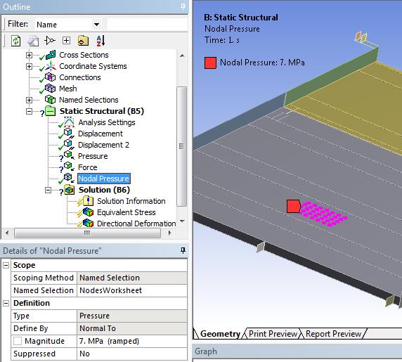
I haven't checked entire thread carefully, but if you have a nodal named selection as shown in one of your replies above you should be able to use nodal pressure. Nodal pressure can only be applied to a nodal named selection, for some more information please check
Ansys Documentation>Mechanical Applications>Mechanical User's Guide> Setting Up Boundary Conditions>Types of Boundary Condition>Direct FE Type Boundary Conditions>Nodal Pressure
I hope that helps!
-
July 2, 2018 at 11:28 am
peteroznewman
SubscriberThanks Aniket,
I see it now! I almost never apply loads direct to nodes but thanhttdt has a good application for it.
You can now easily edit the Upper and Lower Bound values to move the pressure around.
The next improvement would be if you can have those Upper and Lower Bound values be parameters!
Best regards,
Peter
-
July 3, 2018 at 2:51 pm
thanhttdt
SubscriberHi Aniket,
Thanks for your suggestion
However, let me ask you that do I use Node force or Node pressure for Selected nodes?
Hi peteroznewman,
As you said "The next improvement would be if you can have those Upper and Lower Bound values be parameters"
It means that I can use parameter to change the tyre-print easily, right?
Now, I'm looking for new approach by using APDL code in workbench to choose Name selection and apply Node force. However, it's a little bit hard for me right now, so if you have any ideas, please give me some advice.
Many thanks
Best Regards,
-
July 5, 2018 at 10:00 am
Ashish Khemka
Forum Moderator
You may apply the nodal force/ pressure in following way:
1. Create named selection. This creates a nodal component of the nodes in the input file for solver, same as creating a nodal component via CM command.
2. Insert a Commands object under the setup and define the commands:
==============================================
CMSEL for selecting the nodes defined via named selection
F command to apply force
SF command for pressure on nodes
ALLSEL,ALL !Select Everything
===============================================
-
- The topic ‘Load combination and apply pressure’ is closed to new replies.


-
3407
-
1057
-
1051
-
896
-
882

© 2025 Copyright ANSYS, Inc. All rights reserved.


